Peak-to-Average Power Ratio in OFDM Systems
A major problem in multicarrier modulation is the high peak-to-average power ratio
(PAR) that occurs in the modulated signal. Generally, large signal peaks in the transmitted
signal occur when the signals in the K subchannels add constructively in phase.
Such large signal peaks may saturate the power amplifiers at the transmitter, thus causing
intermodulation distortion in the transmitted signal. Intermodulation distortion can
be reduced and often avoided by reducing the power in the transmitted signal and, thus,
operating the power amplifier at the transmitter in its linear range. Such a power reduction
or "power back-off" results in inefficient operation of the OFDM system. For
example, if the PAR is 10 dB, the power back-off may be as much as 10 dB to avoid
intermodulation distortion.
One of the simplest methods to reduce the PAR is to limit the peak amplitude of the
transmitted signal to some value above the average power. However, such amplitude
clipping will result in signal distortion. The following illustrative problem investigates
this approach.
Matlab Coding


 1 % MATLAB script for Illustrative Problem 8.6
 2 clear;
 3 T = 1;
 4 Fs = 200;
 5 t = 0 : 1/(Fs*T) : T-1/(Fs*T);
 6 K = 32;
 7 k = 1 : K-1;
 8 rlz = 20;                   % No. of realizations
 9 PAR = zeros(1,rlz);         % Initialization for speed
10 for j = 1 : rlz
11     theta = pi*floor(rand(1,length(k))/0.25)/2;     % theta takes the possible values 0,TT/ 2, TT, 3 rr / 2, selected pseudorandomly.
12     x = zeros(1,Fs);        % Initialization for speed
13     echo off;
14     for i = 1 : Fs
15         for l = 1 : K-1
16             x(i) = x(i) + cos(2*pi*l*t(i)/T+theta(l));
17         end
18     end
19     echo on;
20     % Calculation of the PAR:
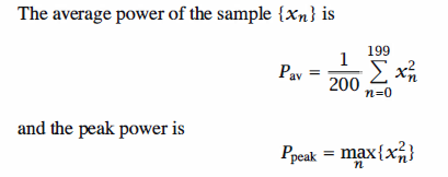
21     P_peak = max(x.^2);
22     P_av = sum(x.^2)/Fs;
23     PAR(j) = P_peak/P_av;
24 end

25 % Plotting the results:
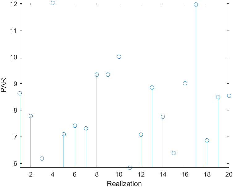
26 stem(PAR)
27 axis([1 20 min(PAR) max(PAR)])
28 xlabel('Realization')
29 ylabel('PAR')


Simulation Result

Reference,
1. <<Contemporary Communication System using MATLAB>> - John G. Proakis