最近买了一块圆形屏幕,驱动IC是GC9A01,自己参考淘宝给的stm32的驱动例程,
在ubuntu下使用IDF开发ESP32,也在windows的vscode内安装IDF开发ESP32,虽然都做到了能显示图片,但是总有一块暗紫色的偏差阴影,也尝试了移植LVGL,都遇到了问题。

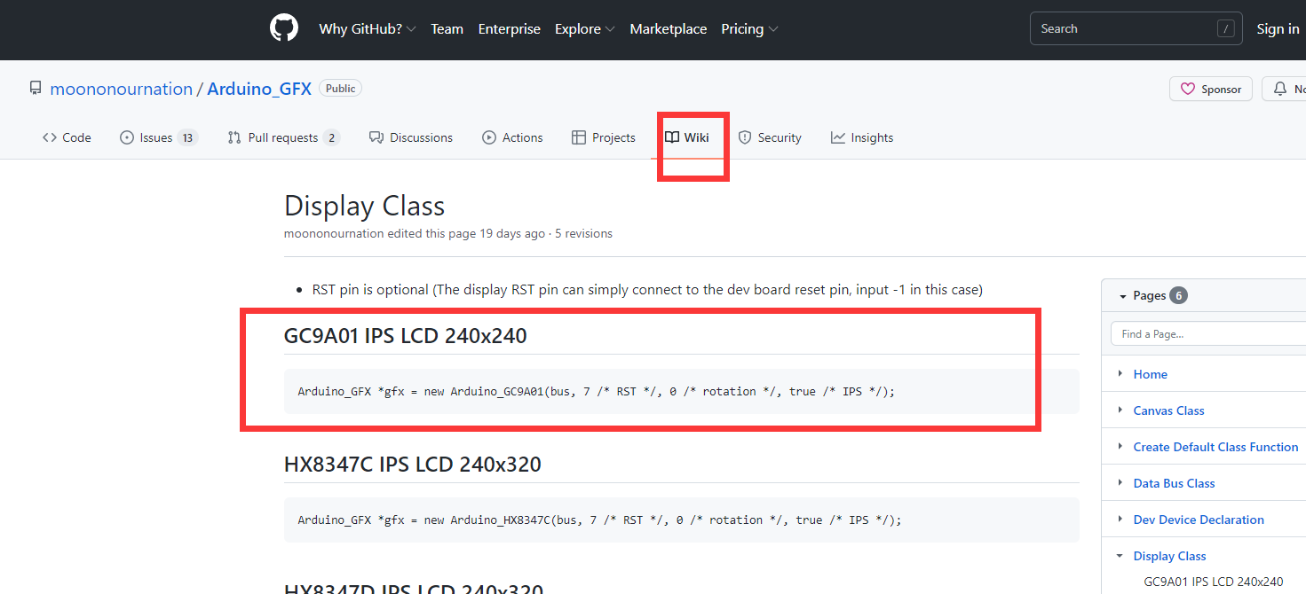
如上图,在网上看到有Arduino的一个TFT LCD的驱动库,已经包含了对该型号屏幕IC的驱动,所以转战Arduino环境,来驱动这块圆形屏幕。
1. 下载Arduino_GFX库
https://github.com/moononournation/Arduino_GFX
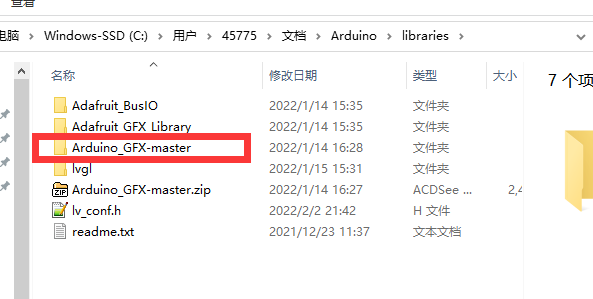
下载好该库后,放置到Arduino的library目录下,如下图所示。这是Arduino的库的默认路径。

2.Arduino GFX库测试
Arduino 的library目录,这个路径内的项目文件都是只读的,不便于我们直接打开内部的示例项目烧录和测试。
将Arduino GFX库内的example文件夹内的HelloWorld文件夹复制到其他路径下,我是复制到了桌面上的smart_screen_001文件夹内,然后打开项目工程HelloWorld.ino文件。

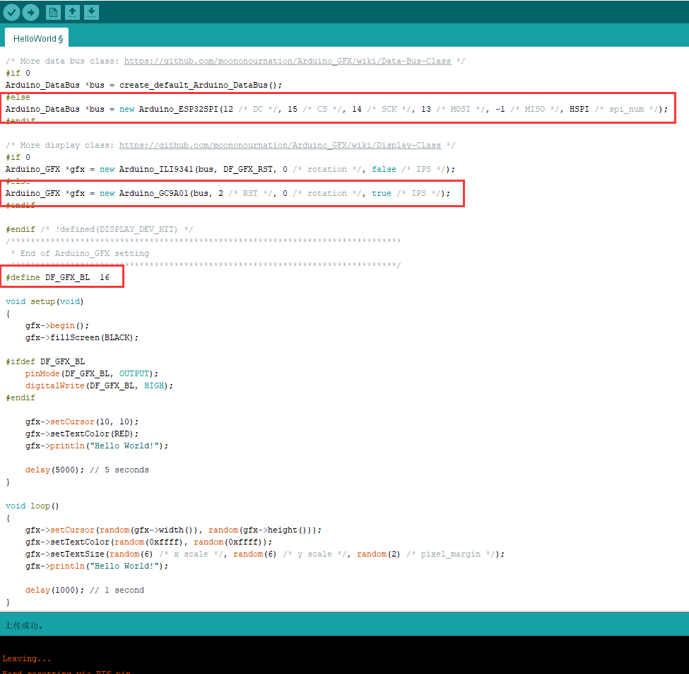
修改三处代码,分别修改DC 以及SPI等脚位,以及RST脚,和背光脚DF_GFX_BL。

上述Arduino+ESP32,驱动GC9A01的源文件:
/*******************************************************************************
 * Start of Arduino_GFX setting
 *
 * Arduino_GFX try to find the settings depends on selected board in Arduino IDE
 * Or you can define the display dev kit not in the board list
 * Defalult pin list for non display dev kit:
 * Arduino Nano, Micro and more: CS:  9, DC:  8, RST:  7, BL:  6
 * ESP32 various dev board     : CS:  5, DC: 27, RST: 33, BL: 22
 * ESP32-C3 various dev board  : CS:  7, DC:  2, RST:  1, BL:  3
 * ESP32-S2 various dev board  : CS: 34, DC: 26, RST: 33, BL: 21
 * ESP8266 various dev board   : CS: 15, DC:  4, RST:  2, BL:  5
 * Raspberry Pi Pico dev board : CS: 17, DC: 27, RST: 26, BL: 28
 * RTL8720 BW16 old patch core : CS: 18, DC: 17, RST:  2, BL: 23
 * RTL8720_BW16 Official core  : CS:  9, DC:  8, RST:  6, BL:  3
 * RTL8722 dev board           : CS: 18, DC: 17, RST: 22, BL: 23
 * RTL8722_mini dev board      : CS: 12, DC: 14, RST: 15, BL: 13
 * Seeeduino XIAO dev board    : CS:  3, DC:  2, RST:  1, BL:  0
 * Teensy 4.1 dev board        : CS: 39, DC: 41, RST: 40, BL: 22
 ******************************************************************************/
#include <Arduino_GFX_Library.h>

/* More dev device declaration: https://github.com/moononournation/Arduino_GFX/wiki/Dev-Device-Declaration */
#if defined(DISPLAY_DEV_KIT)
Arduino_GFX *gfx = create_default_Arduino_GFX();
#else /* !defined(DISPLAY_DEV_KIT) */

/* More data bus class: https://github.com/moononournation/Arduino_GFX/wiki/Data-Bus-Class */
#if 0
Arduino_DataBus *bus = create_default_Arduino_DataBus();
#else
Arduino_DataBus *bus = new Arduino_ESP32SPI(12 /* DC */, 15 /* CS */, 14 /* SCK */, 13 /* MOSI */, -1 /* MISO */, HSPI /* spi_num */);
#endif

/* More display class: https://github.com/moononournation/Arduino_GFX/wiki/Display-Class */
#if 0
Arduino_GFX *gfx = new Arduino_ILI9341(bus, DF_GFX_RST, 0 /* rotation */, false /* IPS */);
#else
Arduino_GFX *gfx = new Arduino_GC9A01(bus, 2 /* RST */, 0 /* rotation */, true /* IPS */);
#endif

#endif /* !defined(DISPLAY_DEV_KIT) */
/*******************************************************************************
 * End of Arduino_GFX setting
 ******************************************************************************/
#define DF_GFX_BL  16

void setup(void)
{
    gfx->begin();
    gfx->fillScreen(BLACK);

#ifdef DF_GFX_BL
    pinMode(DF_GFX_BL, OUTPUT);
    digitalWrite(DF_GFX_BL, HIGH);
#endif

    gfx->setCursor(10, 10);
    gfx->setTextColor(RED);
    gfx->println("Hello World!");

    delay(5000); // 5 seconds
}

void loop()
{
    gfx->setCursor(random(gfx->width()), random(gfx->height()));
    gfx->setTextColor(random(0xffff), random(0xffff));
    gfx->setTextSize(random(6) /* x scale */, random(6) /* y scale */, random(2) /* pixel_margin */);
    gfx->println("Hello World!");

    delay(1000); // 1 second
}
实验现象:

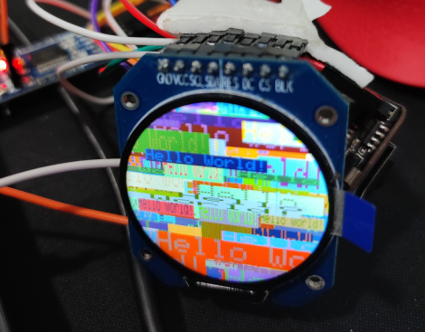
随机弹出了很多不同大小,不同色彩的Hello world,符合示例代码的实现。
这样,Arduino_GFX库就顺利移植好了。
.