1. 理论知识
理论知识请参考:
- 机器人学导论++(原书第3版)_(美)HLHN+J.CRAIG著++贠超等译
- 机器人学课程讲义(丁烨)
- 机器人学课程讲义(赵言正)
2. Matlab Robotics Toolbox安装
上官网:
http://petercorke.com/wordpress/toolboxes/robotics-toolbox
Download RTB-10.3.1 mltbx format (23.2 MB) in MATLAB toolbox format (.mltbx)
将down下来的文件放到一般放untitled.m所在的文件夹内。打开MATLAB运行,显示安装完成即可。
不要下zip,里面的东西各种缺失并且乱七八糟,很难配。
该工具箱内的说明书是robot.pdf
也可查阅 “机器人工具箱简介.ppt”
3. 机器人建模
本仿真程序仿照fanuc_M20ia机器人进行建模。
3.1 利用DH矩阵建立机器人模型(modified)
经测绘,用如下代码建立DH矩阵
使用robot.teach()函数,进行机器人示教
% RobotTeach.m

clc;
%             theta   d         a        alpha     offset
ML1 =  Link([ 0,      0.4967,   0,       0,        0], 'modified');
ML2 =  Link([ -pi/2,  -0.18804, 0.2,     3*pi/2,   0], 'modified');
ML3 =  Link([ 0,      0.17248,  0.79876, 0 ,       0], 'modified');
ML4 =  Link([ 0,      0.98557,  0.25126, 3*pi/2,   0], 'modified');
ML5 =  Link([ 0,      0,        0,       pi/2 ,    0], 'modified');
ML6 =  Link([ 0,      0,        0,       pi/2 ,    0], 'modified');

robot = SerialLink([ML1 ML2 ML3 ML4 ML5 ML6],'name','Fanuc M20ia');
robot.teach(); %可以自由拖动的关节角度

% EOF
效果如下:

3.2 机器人参数设定
在做仿真计算时,需要设定各个关节的运动学与动力学参数
质量属性可以在SolidWorks中指定材质后,在“评估-质量属性”中查看
运动学参数:
%  theta    关节角度
%  d        连杆偏移量
%  a        连杆长度
%  alpha    连杆扭角
%  sigma    旋转关节为0,移动关节为1
%  mdh      标准的D&H为0,否则为1
%  offset   关节变量偏移量
%  qlim     关节变量范围[min max]
动力学参数:
%  m        连杆质量
%  r        连杆相对于坐标系的质心位置3x1
%  I        连杆的惯性矩阵(关于连杆重心)3x3
%  B        粘性摩擦力(对于电机)1x1或2x1
%  Tc       库仑摩擦力1x1或2x1
电机和传动参数:
%  G        齿轮传动比
%  Jm       电机惯性矩(对于电机)
完整的机器人建模代码
clear;
clc;
%             theta   d         a        alpha     offset
ML1 =  Link([ 0,      0.4967,   0,       0,        0], 'modified');
ML2 =  Link([ -pi/2,  -0.18804, 0.2,     3*pi/2,   0], 'modified');
ML3 =  Link([ 0,      0.17248,  0.79876, 0 ,       0], 'modified');
ML4 =  Link([ 0,      0.98557,  0.25126, 3*pi/2,   0], 'modified');
ML5 =  Link([ 0,      0,        0,       pi/2 ,    0], 'modified');
ML6 =  Link([ 0,      0,        0,       pi/2 ,    0], 'modified');

%配置机器人参数
ML1.m = 20.8;
ML2.m = 17.4;
ML3.m = 4.8;
ML4.m = 0.82;
ML5.m = 0.34;
ML6.m = 0.09;

ML1.r = [ 0    0    0 ];
ML2.r = [ -0.3638  0.006    0.2275];
ML3.r = [ -0.0203  -0.0141  0.070];
ML4.r = [ 0    0.019    0];
ML5.r = [ 0    0        0];
ML6.r = [ 0    0        0.032];

ML1.I = [  0         0.35         0         0         0         0];
ML2.I = [  0.13      0.524        0.539     0         0         0];
ML3.I = [  0.066     0.086        0.0125    0         0         0];
ML4.I = [  1.8e-3  1.3e-3  1.8e-3  0         0         0];
ML5.I = [  0.3e-3  0.4e-3  0.3e-3   0         0         0];
ML6.I = [  0.15e-3 0.15e-3 0.04e-3  0         0         0];

ML1.Jm =  200e-6;
ML2.Jm =  200e-6;
ML3.Jm =  200e-6;
ML4.Jm =  33e-6;
ML5.Jm =  33e-6;
ML6.Jm =  33e-6;

ML1.G =  -62.6111;
ML2.G =  107.815;
ML3.G =  -53.7063;
ML4.G =  76.0364;
ML5.G =  71.923;
ML6.G =  76.686;

% viscous friction (motor referenced)
ML1.B =   1.48e-3;
ML2.B =   0.817e-3;
ML3.B =   1.38e-3;
ML4.B =   71.2e-6;
ML5.B =   82.6e-6;
ML6.B =   36.7e-6;

% Coulomb friction (motor referenced)
ML1.Tc = [ 0.395        -0.435];
ML2.Tc = [ 0.126        -0.071];
ML3.Tc = [ 0.132        -0.105];
ML4.Tc = [ 11.2e-3      -16.9e-3];
ML5.Tc = [ 9.26e-3      -14.5e-3];
ML6.Tc = [ 3.96e-3      -10.5e-3];

robot=SerialLink([ML1 ML2 ML3 ML4 ML5 ML6],'name','Fanuc M20ia');% 注意:这句话最后写,不然会报错
4. 正向运动学与机器人工作空间的求取
4.1 正向运动学
串联链式操作器的正向运动学问题,是在给定所有关节位置和所有连杆几何参数的情况下,求取末端相对于基座的位置和姿态。
末端执行器相对于基座的变换矩阵
(_60)T=(_10)T(_21)T(_32)T(_43)T(_54)T(_6^5)T
该变换矩阵是关于6个关节变量θ_i的函数,在给定一组θ下,机器人末端连杆在笛卡尔坐标系里的位置和姿态都可以计算得到。
4.2 采用蒙特卡洛法对机器人的工作空间进行仿真分析
机器人末端执行器能够到达的空间位置点的集合构成了其工作空间范围。现在采用蒙特卡洛法对机器人的工作空间进行分析。蒙特卡洛法是一种借助于随机抽样来解决数学问题的数值方法,具体求解步骤如下:
1)在机器人正运动学方程中,可以得到末端执行器在参考坐标系中相对基坐标系的位置向量。
2)根据机器人关节变量取值范围,在MATLAB中生成各关节变量随机值。
θi=θimin+(θimax-θimin)×RAND(N,1)
3)将所有关节变量的随机值代入运动学方程的位置向量中从而得到由随机点构成的云图,就构成了机器人的蒙特卡洛工作空间。
代码如下:
%ShowWorkspace.m

clear;
clc;
%             theta   d         a        alpha     offset
ML1 =  Link([ 0,      0.4967,   0,       0,        0], 'modified');
ML2 =  Link([ -pi/2,  -0.18804, 0.2,     3*pi/2,   0], 'modified');
ML3 =  Link([ 0,      0.17248,  0.79876, 0 ,       0], 'modified');
ML4 =  Link([ 0,      0.98557,  0.25126, 3*pi/2,   0], 'modified');
ML5 =  Link([ 0,      0,        0,       pi/2 ,    0], 'modified');
ML6 =  Link([ 0,      0,        0,       pi/2 ,    0], 'modified');

robot = SerialLink([ML1 ML2 ML3 ML4 ML5 ML6],'name','Fanuc M20ia');
robot.plot([0,0,0,0,0,0]);
hold on;

N=3000;                                              %随机次数
theta1min = -180/180*pi; theta1max = 180/180*pi;
theta2min = -180/180*pi; theta2max = 0/180*pi;
theta3min = -90/180*pi;  theta3max = 90/180*pi;
theta4min = -180/180*pi; theta4max = 180/180*pi;
theta5min = -135/180*pi; theta5max = 135/180*pi;
theta6min = -180/180*pi; theta6max = 180/180*pi;

theta1=theta1min+(theta1max-theta1min)*rand(N,1); %关节1限制
theta2=theta2min+(theta2max-theta2min)*rand(N,1); %关节2限制
theta3=theta3min+(theta3max-theta3min)*rand(N,1); %关节3限制
theta4=theta4min+(theta4max-theta4min)*rand(N,1); %关节4限制
theta5=theta5min+(theta5max-theta5min)*rand(N,1); %关节5限制
theta6=theta6min+(theta6max-theta6min)*rand(N,1); %关节6限制

for n=1:N
q = zeros(1,6);
q(1) = theta1(n);
q(2) = theta2(n);
q(3) = theta3(n);
q(4) = theta4(n);
q(5) = theta5(n);
q(6) = theta6(n);
modmyt06 = robot.fkine(q);
plot3(modmyt06.t(1),modmyt06.t(2),modmyt06.t(3),'b.','MarkerSize',0.5);
end

%EOF
效果如下图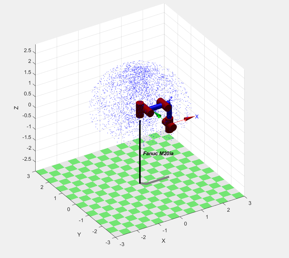
点的疏密程度代表了机械臂末端的执行器出现在这个点的概率大小。
5. 逆向运动学
从ShowWorkspace.m的运行结果中提取两个末端执行器的位姿
注意:modmyt06中有四个向量t,n,o,a
T = [ n o a t ]
[ 0 0 0 1 ]
逆向运动学的理论知识参见机器人学课本。对于6自由度球腕关节的机械臂,必有解析解,可以用ikine6s()反解,但是必须是标准DH描述下
所以采用ikine()迭代法求解这两个位姿的逆向角度
%给定末端执行器的初始位置
p1 =[
0.617222144    0.465154659    -0.634561241    -0.254420286
-0.727874557   0.031367208	  -0.684992502	  -1.182407321
-0.298723039   0.884673523	  0.357934776	  -0.488241553
0	           0	          0	              1
];

%给定末端执行器的终止位置
p2 = [
-0.504697849	-0.863267623	-0.007006569	0.664185871
-0.599843651	0.356504321	    -0.716304589	-0.35718173
0.620860432	    -0.357314539	-0.697752567	2.106929688
0	            0	            0	            1
];


%利用运动学反解ikine求解各关节转角
% Inverse kinematics by optimization without joint limits
% q = R.ikine(T) are the joint coordinates (1 N) corresponding to the robot end-effector
% pose T which is an SE3 object or homogenenous transform matrix (4 4), and N is the
% number of robot joints.

init_ang = robot.ikine(p1);%使用运动学迭代反解的算法计算得到初始的关节角度
targ_ang = robot.ikine(p2);%使用运动学迭代反解的算法计算得到目标关节角度
6. 正向动力学与逆向动力学
6.1 正向动力学
已知关节力确定机械臂运动
qdd=p560.accel(qn,qz,ones(1,6)); %给定位置qn,速度qz,力矩ones(1,6 ),求加速度
6.2 逆向动力学
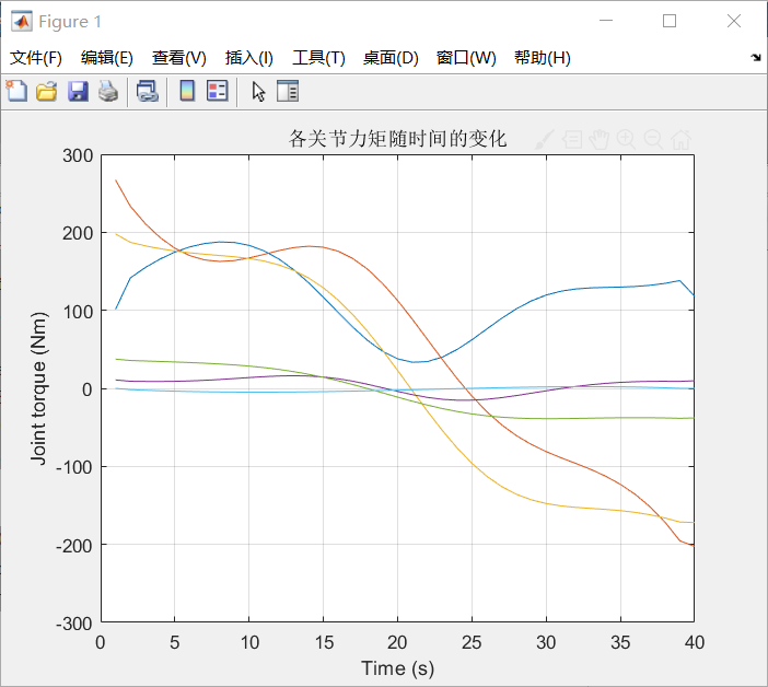
已知各个关节的角度,角速度和角加速度,以及各机械臂的运动参数,求取各关节的力矩
代码如下:
%Dynamics.m

%(...)机器人动力学建模部分略去

%给定末端执行器的初始位置
p1 =[
0.617222144    0.465154659    -0.634561241    -0.254420286
-0.727874557   0.031367208	  -0.684992502	  -1.182407321
-0.298723039   0.884673523	  0.357934776	  -0.488241553
0	           0	          0	              1
];

%给定末端执行器的终止位置
p2 = [
-0.504697849	-0.863267623	-0.007006569	0.664185871
-0.599843651	0.356504321	    -0.716304589	-0.35718173
0.620860432	    -0.357314539	-0.697752567	2.106929688
0	            0	            0	            1
];

init_ang = robot.ikine(p1);%使用运动学迭代反解的算法计算得到初始的关节角度
targ_ang = robot.ikine(p2);%使用运动学迭代反解的算法计算得到目标关节角度

step=40;
[q,qd,qdd] = jtraj(init_ang, targ_ang, step);%关节空间内的S曲线插补法,q qd qdd分别为各个关节的角度,角速度和角加速度


% 已知关节的角度、角速度、角加速度等信息,求各关节所需提供的力矩
% Inverse dynamics
% tau = R.rne(q, qd, qdd, options) is the joint torque required for the robot R to achieve
% the specified joint position q (1 N), velocity qd (1 N) and acceleration qdd (1 N),
% where N is the number of robot joints.

W = [0 0 -20*9.8 20*9.8*0.2 0 0]; %外力负载

tau = robot.rne(q,qd,qdd,'fext',W);

i=1:6;
plot(tau(:,i));
xlabel('Time (s)');
ylabel('Joint torque (Nm)');
title('各关节力矩随时间的变化');
grid on;

%EOF
效果如下:
7. 轨迹生成
轨迹规划是根据作业任务要求事先规定机器人的操作顺序和动作过程,轨迹规划分为关节空间和笛卡尔空间轨迹规划。
- 确定末端操作器的初始位置和目标位置
- 根据逆运动学求出各关节的初始角度和目标角度
- 估计规划,求出各关节的角度变化曲线
- 进行运动控制,使机器人按照轨迹规划结果运动
7.1 关节空间轨迹规划
思路:给定起始点p1,目标点p2, 利用运动学反解的得到q1,q2,在关节空间内利用五次多项式做插补,得到[q, qd, qdd],再通过运动学正解,得到末端执行器的位置,线速度与角速度的值
代码如下
%TrajectoryGeneration_p2p_lnksps.m

clear;
clc;
%             theta   d         a        alpha     offset
ML1 =  Link([ 0,      0.4967,   0,       0,        0], 'modified');
ML2 =  Link([ -pi/2,  -0.18804, 0.2,     3*pi/2,   0], 'modified');
ML3 =  Link([ 0,      0.17248,  0.79876, 0 ,       0], 'modified');
ML4 =  Link([ 0,      0.98557,  0.25126, 3*pi/2,   0], 'modified');
ML5 =  Link([ 0,      0,        0,       pi/2 ,    0], 'modified');
ML6 =  Link([ 0,      0,        0,       pi/2 ,    0], 'modified');
robot = SerialLink([ML1 ML2 ML3 ML4 ML5 ML6],'name','Fanuc M20ia');

%给定末端执行器的初始位置
p1 =[
0.617222144    0.465154659    -0.634561241    -0.254420286
-0.727874557   0.031367208	  -0.684992502	  -1.182407321
-0.298723039   0.884673523	  0.357934776	  -0.488241553
0	           0	          0	              1
];

%给定末端执行器的终止位置
p2 = [
-0.504697849	-0.863267623	-0.007006569	0.664185871
-0.599843651	0.356504321	    -0.716304589	-0.35718173
0.620860432	    -0.357314539	-0.697752567	2.106929688
0	            0	            0	            1
];


%利用运动学反解ikine求解各关节转角
% Inverse kinematics by optimization without joint limits
% q = R.ikine(T) are the joint coordinates (1 N) corresponding to the robot end-effector
% pose T which is an SE3 object or homogenenous transform matrix (4 4), and N is the
% number of robot joints.

init_ang = robot.ikine(p1);%使用运动学迭代反解的算法计算得到初始的关节角度
targ_ang = robot.ikine(p2);%使用运动学迭代反解的算法计算得到目标关节角度

%利用五次多项式计算关节速度和加速度
% Compute a joint space trajectory
% [q,qd,qdd] = jtraj(q0, qf, m) is a joint space trajectory q (m N) where the joint
% coordinates vary from q0 (1 N) to qf (1 N). A quintic (5th order) polynomial is used
% with default zero boundary conditions for velocity and acceleration. Time is assumed
% to vary from 0 to 1 in m steps. Joint velocity and acceleration can be optionally returned
% as qd (m N) and qdd (m N) respectively. The trajectory q, qd and qdd are m N
% matrices, with one row per time step, and one column per joint.
step=40;
[q,qd,qdd] = jtraj(init_ang, targ_ang, step);

% 显示机器人姿态随时间的变化
subplot(3,3,[1,4,7]);
robot.plot(q);

%显示机器人关节运动状态
subplot(3,3,2);
i=1:6;
plot(q(:,i));
title('初始位置      各关节角度随时间的变化      目标位置');
grid on;
subplot(3,3,5);
i=1:6;
plot(qd(:,i));
title('各关节角速度随时间的变化');
grid on;
subplot(3,3,8);
i=1:6;
plot(qdd(:,i));
title('各关节角加速度随时间的变化');
grid on;

%显示末端执行器的位置
subplot(3,3,3);
hold on
grid on
title('末端执行器在三维空间中的位置变化');
for i=1:step
position = robot.fkine(q(i,:));
plot3(position.t(1),position.t(2),position.t(3),'b.','MarkerSize',5);
end

%显示末端执行器的线速度与角速度
% Jacobian in world coordinates
% j0 = R.jacob0(q, options) is the Jacobian matrix (6 N) for the robot in pose q (1 N),
% and N is the number of robot joints. The manipulator Jacobian matrix maps joint
% velocity to end-effector spatial velocity V = j0*QD expressed in the world-coordinate frame.
subplot(3,3,6);
hold on
grid on
title('末端执行器速度大小随时间的变化');
vel = zeros(step,6);
vel_velocity = zeros(step,1);
vel_angular_velocity = zeros(step,1);
for i=1:step
vel(i,:) = robot.jacob0(q(i,:))*qd(i,:)';
vel_velocity(i) = sqrt(vel(i,1)^2+vel(i,2)^2+vel(i,3)^2);
vel_angular_velocity(i) = sqrt(vel(i,4)^2+vel(i,5)^2+vel(i,3)^6);
end
x = linspace(1,step,step);
plot(x,vel_velocity);

subplot(3,3,9);
hold on
grid on
title('末端执行器角速度大小随时间的变化');
x = linspace(1,step,step);
plot(x,vel_angular_velocity);

%EOF
效果如下
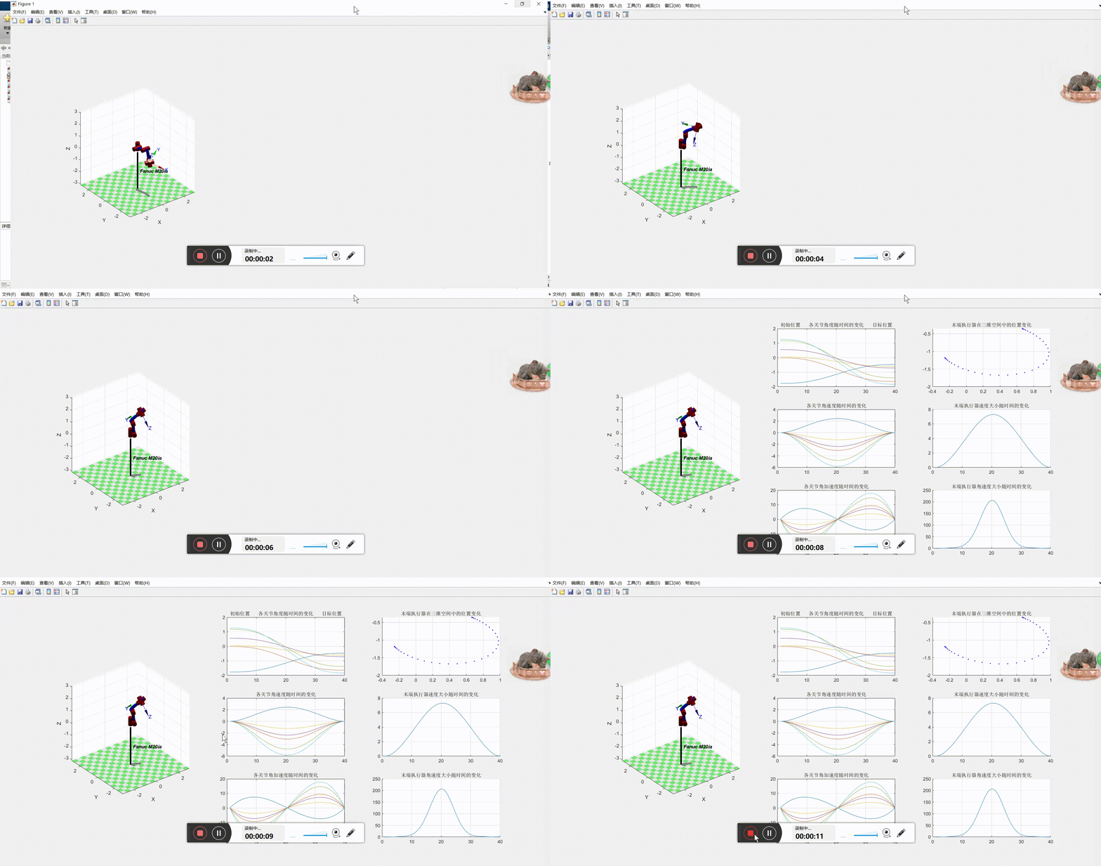
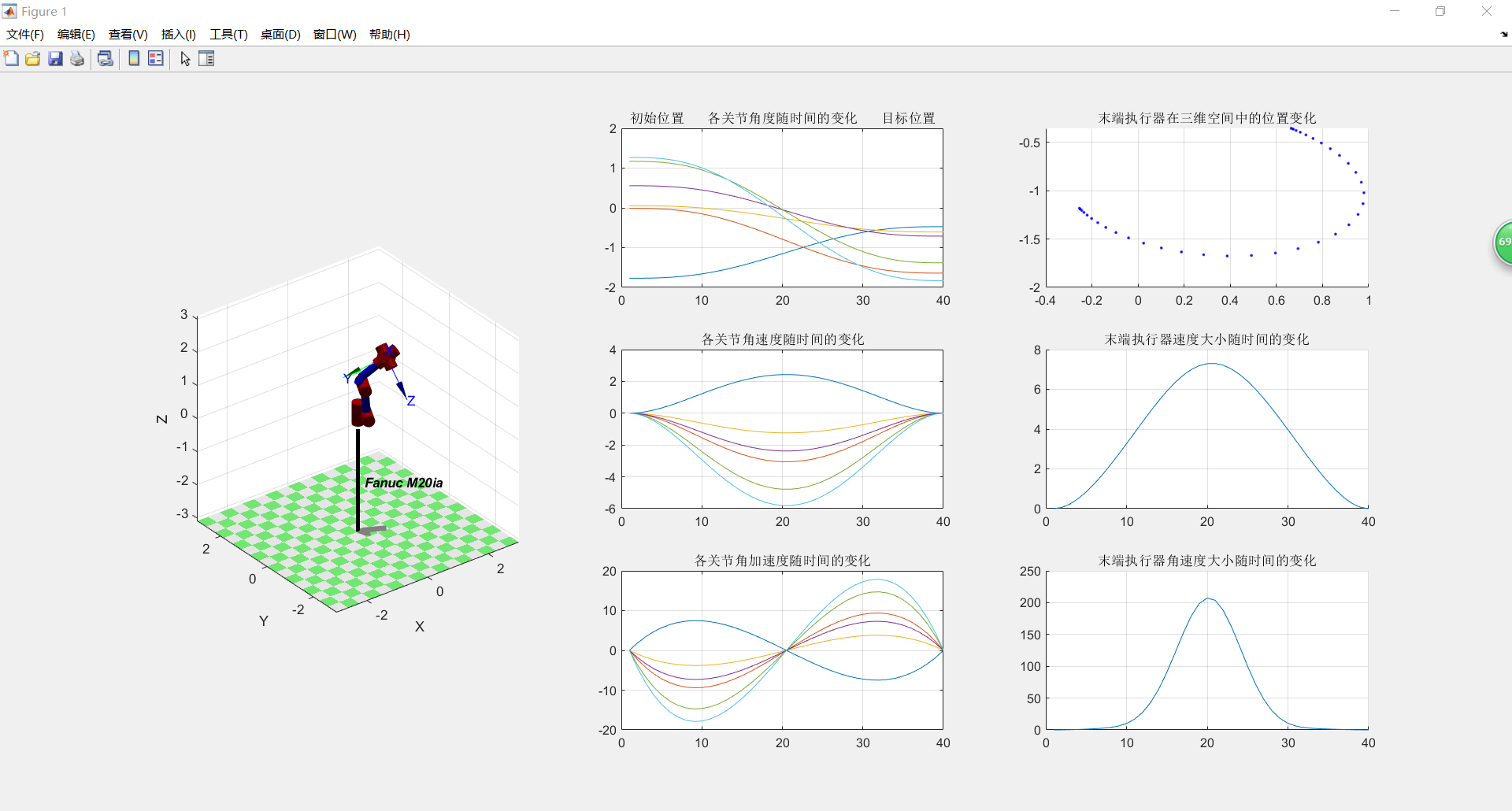
从图中解得的曲线证明:在关节空间内进行五次多项式插补得到的机械臂关节运动学曲线较为平滑,而且末端执行器的速度和角速度随时间的变化都比较均匀而平滑。
7.2 笛卡尔空间轨迹规划
思路:给定起始点p1,目标点p2, 利用梯形速度插补得到末端坐标系位姿矩阵Tc随时间的变化,再对每一个Tc通过运动学反解,得到各个关节的角度,并估算各个关节的角速度与角加速度的值,以及末端执行器的速度与加速度的大小。
代码如下
%TrajectoryGeneration_p2p_Cartesian.m

clear;
clc;
%             theta   d         a        alpha     offset
ML1 =  Link([ 0,      0.4967,   0,       0,        0], 'modified');
ML2 =  Link([ -pi/2,  -0.18804, 0.2,     3*pi/2,   0], 'modified');
ML3 =  Link([ 0,      0.17248,  0.79876, 0 ,       0], 'modified');
ML4 =  Link([ 0,      0.98557,  0.25126, 3*pi/2,   0], 'modified');
ML5 =  Link([ 0,      0,        0,       pi/2 ,    0], 'modified');
ML6 =  Link([ 0,      0,        0,       pi/2 ,    0], 'modified');
robot = SerialLink([ML1 ML2 ML3 ML4 ML5 ML6],'name','Fanuc M20ia');

%给定末端执行器的初始位置
p1 =[
0.617222144    0.465154659    -0.634561241    -0.254420286
-0.727874557   0.031367208	  -0.684992502	  -1.182407321
-0.298723039   0.884673523	  0.357934776	  -0.488241553
0	           0	          0	              1
];

%给定末端执行器的终止位置
p2 = [
-0.504697849	-0.863267623	-0.007006569	0.664185871
-0.599843651	0.356504321	    -0.716304589	-0.35718173
0.620860432	    -0.357314539	-0.697752567	2.106929688
0	            0	            0	            1
];


%在笛卡尔空间坐标系内,根据梯形速度生成轨迹
% Cartesian trajectory between two poses
% tc = ctraj(T0, T1, n) is a Cartesian trajectory (4 4 n) from pose T0 to T1 with n
% points that follow a trapezoidal velocity profile along the path. The Cartesian trajectory
% is a homogeneous transform sequence and the last subscript being the point index, that
% is, T(:,:,i) is the i^th point along the path.

step = 40;
Tc = ctraj(p1,p2,step);

% Inverse kinematics by optimization without joint limits
% q = R.ikine(T) are the joint coordinates (1 N) corresponding to the robot end-effector
% pose T which is an SE3 object or homogenenous transform matrix (4 4), and N is the
% number of robot joints.

% 显示机器人姿态随时间的变化
subplot(3,3,[1,4,7]);
q = zeros(step,6);
for i = 1:step
q(i,:) = robot.ikine(Tc(:,:,i));
end
robot.plot(q);

qd = zeros(step-1,6);
for i = 2:step
    qd(i,1) = q(i,1)-q(i-1,1);
    qd(i,2) = q(i,2)-q(i-1,2);
    qd(i,3) = q(i,3)-q(i-1,3);
    qd(i,4) = q(i,4)-q(i-1,4);
    qd(i,5) = q(i,5)-q(i-1,5);
    qd(i,6) = q(i,6)-q(i-1,6);
end

qdd = zeros(step-2,6);
for i = 2:step-1
    qdd(i,1) = qd(i,1)-qd(i-1,1);
    qdd(i,2) = qd(i,2)-qd(i-1,2);
    qdd(i,3) = qd(i,3)-qd(i-1,3);
    qdd(i,4) = qd(i,4)-qd(i-1,4);
    qdd(i,5) = qd(i,5)-qd(i-1,5);
    qdd(i,6) = qd(i,6)-qd(i-1,6);
end
%显示机器人关节运动状态
subplot(3,3,2);
i=1:6;
plot(q(:,i));
title('初始位置      各关节角度随时间的变化      目标位置');
grid on;
subplot(3,3,5);
i=1:6;
plot(qd(:,i));
title('各关节角速度随时间的变化');
grid on;
subplot(3,3,8);
i=1:6;
plot(qdd(:,i));
title('各关节角加速度随时间的变化');
grid on;

%显示末端执行器的位置
subplot(3,3,3);
hold on
grid on
title('末端执行器在三维空间中的位置变化');
for i=1:step
plot3(Tc(1,4,i),Tc(2,4,i),Tc(3,4,i),'b.','MarkerSize',5);
end

%显示末端执行器的速度
subplot(3,3,6);
hold on
grid on
title('末端执行器速度大小随时间的变化');
vel_velocity = zeros(step,1);
for i=2:step
vel_velocity(i) = sqrt((Tc(1,4,i)-Tc(1,4,i-1))^2+(Tc(2,4,i)-Tc(2,4,i-1))^2+(Tc(3,4,i)-Tc(3,4,i-1))^2);
end
x = linspace(1,step,step);
plot(x,vel_velocity);

%显示末端执行器的加速度
subplot(3,3,9);
hold on
grid on
title('末端执行器加速度大小随时间的变化');
vel_acceleration= zeros(step-2,1);
for i=3:step
vel_acceleration(i-2) = sqrt((Tc(1,4,i)-Tc(1,4,i-1)-(Tc(1,4,i-1)-Tc(1,4,i-2))   )^2+( Tc(2,4,i)-Tc(2,4,i-1)-(Tc(2,4,i-1)-Tc(2,4,i-2)) )^2+( Tc(3,4,i)-Tc(3,4,i-1)-(Tc(3,4,i-1)-Tc(3,4,i-2)))^2);
end
x = linspace(1,step-2,step-2);
plot(x,vel_acceleration);

%EOF
效果如下:
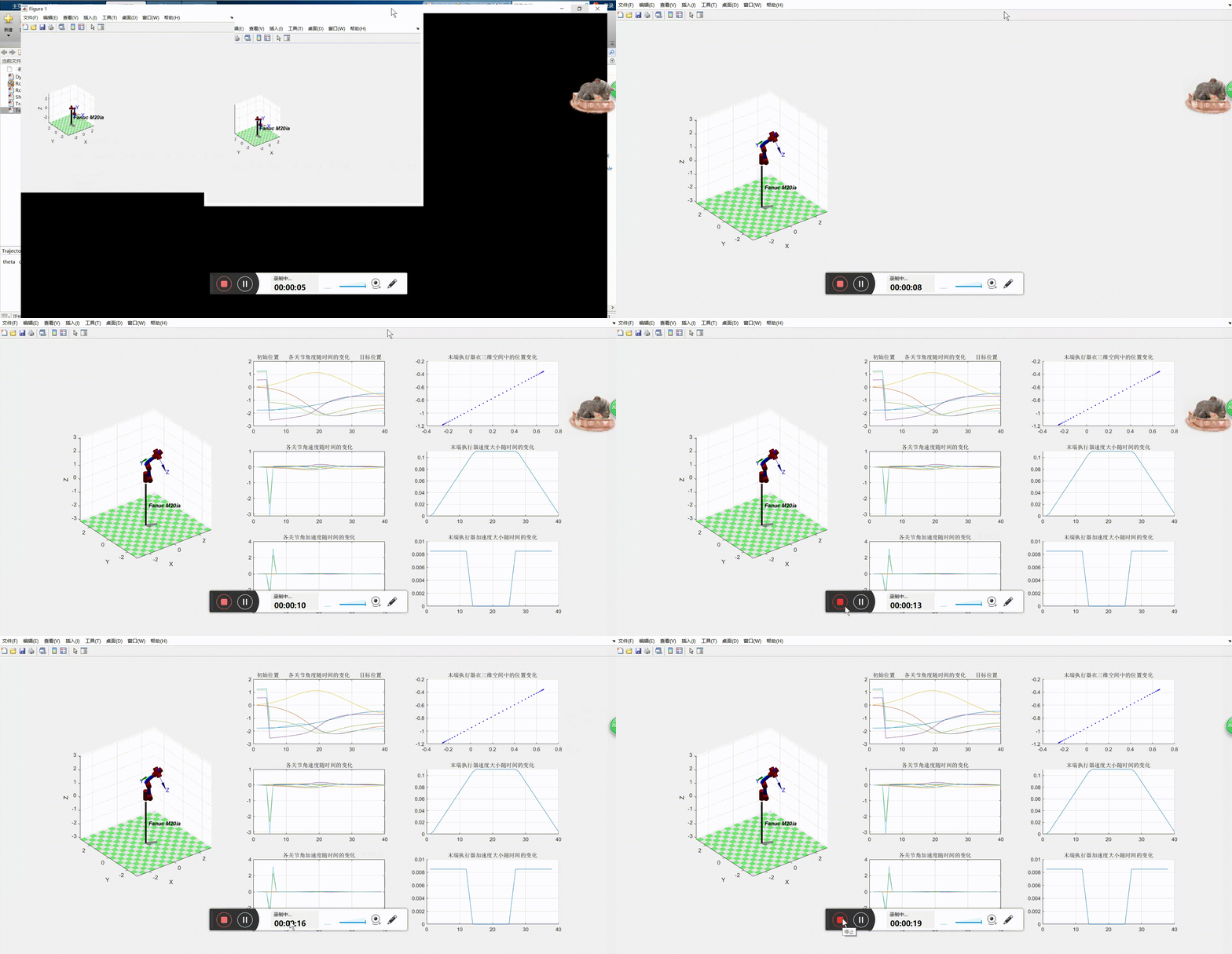

从图中解得的曲线证明:在笛卡尔坐标系内做速度的梯形插补,其末端执行器的轨迹是一条直线,速度是一个梯形,即为匀加速,匀速,匀减速过程。加速度在两个值之间突变,机械臂存在振动和柔性冲击。另外,关节空间内的曲线也出现尖锐的突变点,说明在这段范围内机械臂的运动经过奇点附近,即使末端执行器的速度比较小,但是关节的角速度和角加速度却急剧变化。
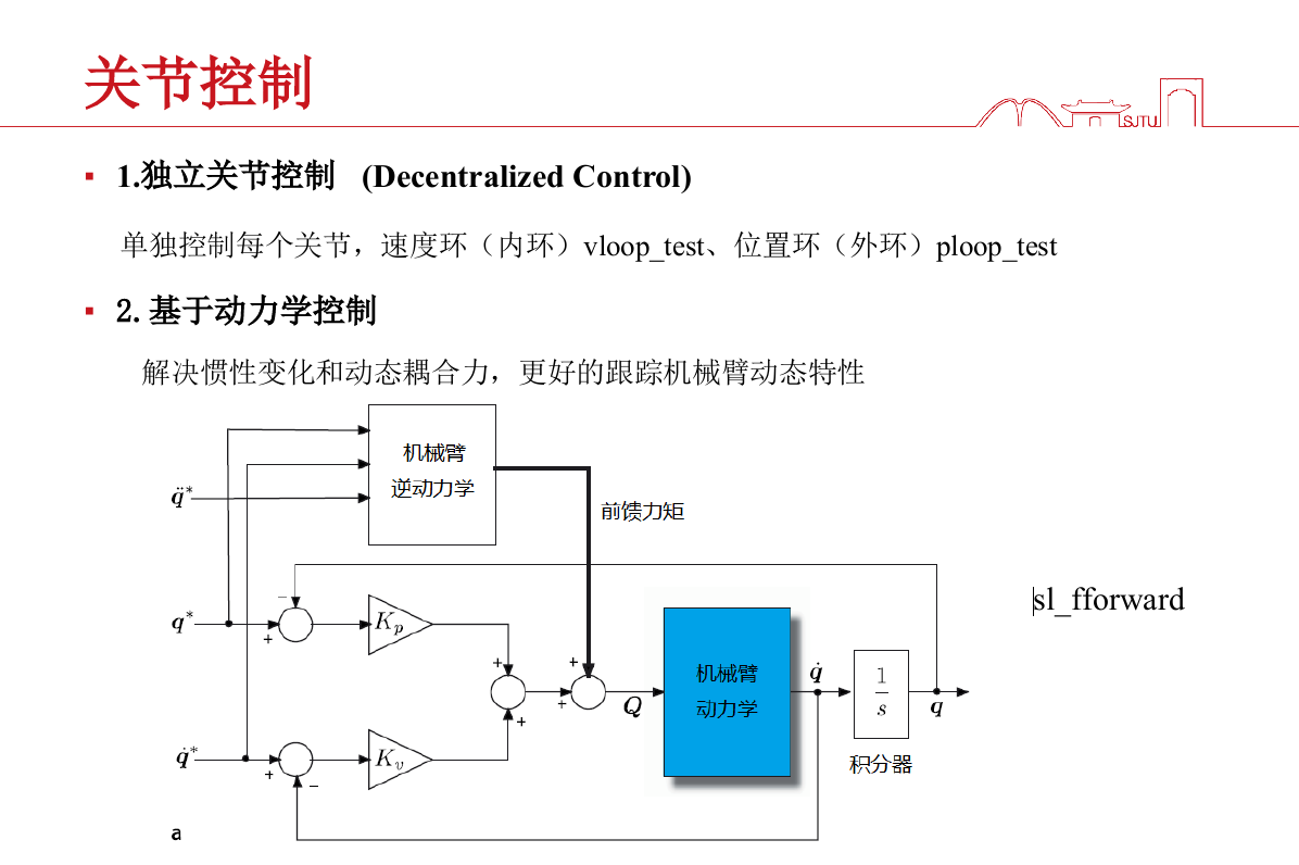
8. 关节控制
