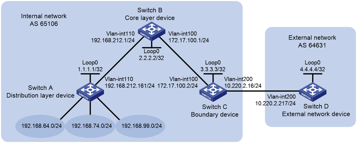
1.组网需求
通过在边界设备Switch C和外部网络设备Switch D之间建立EBGP连接,实现公司内部网络与外部网络的互通。
在公司内部,核心层设备Switch B与汇聚层设备Switch A之间配置静态路由,Switch B与Switch C之间配置OSPF,并在OSPF路由中引入静态路由,以实现公司内部网络的互通。
公司内部网络包括三个网段:192.168.64.0/24、192.168.74.0/24和192.168.99.0/24。在Switch C上配置路由聚合,将这三个网段的路由聚合为一条路由,以减少通过BGP发布的路由数量。

2.配置步骤
1)在Switch A和Switch B之间配置静态路由
# 在Switch A上配置缺省路由,下一跳为Switch B。
[SwitchA] ip route-static 0.0.0.0 0 192.168.212.1

# 在Switch B上配置静态路由,到达目的网络192.168.64.0/24、192.168.74.0/24和192.168.99.0/24的路由下一跳均为Switch A。

[SwitchB] ip route-static 192.168.64.0 24 192.168.212.161
[SwitchB] ip route-static 192.168.74.0 24 192.168.212.161
[SwitchB] ip route-static 192.168.99.0 24 192.168.212.161
2)在Switch B和Switch C之间配置OSPF,并引入静态路由
# 在Switch B上配置OSPF发布本地网段路由,并引入静态路由
[SwitchB] ospf
[SwitchB-ospf-1] area 0
[SwitchB-ospf-1-area-0.0.0.0] network 172.17.100.0 0.0.0.255
[SwitchB-ospf-1-area-0.0.0.0] quit
[SwitchB-ospf-1] import-route static

# 在Switch C上配置OSPF发布本地网段路由。
[SwitchC] ospf
[SwitchC-ospf-1] area 0
[SwitchC-ospf-1-area-0.0.0.0] network 172.17.100.0 0.0.0.255
[SwitchC-ospf-1-area-0.0.0.0] network 10.220.2.0 0.0.0.255
# 在Switch C上查看路由表信息,可以看到Switch C通过OSPF学习到了到达192.168.64.0/24、192.168.74.0/24和192.168.99.0/24网段的路由
[SwitchC] display ip routing-table protocol ospf
Summary count : 5
 OSPF Routing table Status : <Active>
Summary count : 3
Destination/Mask   Proto   Pre Cost        NextHop         Interface
192.168.64.0/24    O_ASE2  150 1           172.17.100.1    Vlan100
192.168.74.0/24    O_ASE2  150 1           172.17.100.1    Vlan100
192.168.99.0/24    O_ASE2  150 1           172.17.100.1    Vlan100

OSPF Routing table Status : <Inactive>
Summary count : 2
Destination/Mask   Proto   Pre Cost        NextHop         Interface
10.220.2.0/24      O_INTRA 10  1           10.220.2.16     Vlan200
172.17.100.0/24    O_INTRA 10  1           172.17.100.2    Vlan100
3)在Switch C和Switch D之间配置BGP,并引入OSPF路由
# 在Switch C上配置Switch D为其EBGP对等体,并引入OSPF路由[SwitchC] bgp 65106
[SwitchC-bgp-default] router-id 3.3.3.3
[SwitchC-bgp-default] peer 10.220.2.217 as-number 64631
[SwitchC-bgp-default] address-family ipv4 unicast
[SwitchC-bgp-default-ipv4] peer 10.220.2.217 enable
[SwitchC-bgp-default-ipv4] import-route ospf

# 在Switch D上配置Switch C为其EBGP对等体
[SwitchD] bgp 64631
[SwitchD-bgp-default] router-id 4.4.4.4
[SwitchD-bgp-default] peer 10.220.2.16 as-number 65106
[SwitchD-bgp-default] address-family ipv4 unicast
[SwitchD-bgp-default-ipv4] peer 10.220.2.16 enable
# 在Switch D上查看路由表信息,可以看到Switch D通过BGP学习到了到达192.168.64.0/24、192.168.74.0/24和192.168.99.0/24三个网段的路由。
[SwitchD] display ip routing-table protocol bgp
Summary count : 3
BGP Routing table Status : <Active>
Summary count : 3
Destination/Mask   Proto   Pre Cost        NextHop         Interface
192.168.64.0/24    BGP     255 1           10.220.2.16     Vlan200
192.168.74.0/24    BGP     255 1           10.220.2.16     Vlan200
192.168.99.0/24    BGP     255 1           10.220.2.16     Vlan200
BGP Routing table Status : <Inactive>
Summary count : 0
完成上述配置后,在Switch D上可以ping通192.168.64.0/24、192.168.74.0/24和192.168.99.0/24网段内的主机。
4)在Switch C上配置路由聚合
# 在Switch C上将路由192.168.64.0/24、192.168.74.0/24和192.168.99.0/24聚合为192.168.64.0/18,并抑制发布具体路由。
[SwitchC-bgp-default-ipv4] aggregate 192.168.64.0 18 detail-suppressed
3.配置验证
# 在Switch C上查看路由表信息,可以看到Switch C上产生了一条聚合路由192.168.64.0/18,该聚合路由的出接口为Null0。
[SwitchC] display ip routing-table | include 192.168
192.168.64.0/18    BGP     130 0           127.0.0.1       NULL0
192.168.64.0/24    OSPF    150 1           172.17.100.1    Vlan100
192.168.74.0/24    OSPF    150 1           172.17.100.1    Vlan100
192.168.99.0/24    OSPF    150 1           172.17.100.1    Vlan100

# 在Switch D上查看路由表信息,可以看到Switch D上到达公司内部三个网络的路由聚合为一条路由192.168.64.0/18。
[SwitchD] display ip routing-table protocol bgp
Summary count : 1
BGP Routing table Status : <Active>
Summary count : 1
Destination/Mask   Proto   Pre Cost        NextHop         Interface
192.168.64.0/18    BGP     255 0           10.220.2.16     Vlan200
BGP Routing table Status : <Inactive>
Summary count : 0
完成上述配置后,成功实现了路由聚合。并且,在Switch D上可以ping通192.168.64.0/24、192.168.74.0/24和192.168.99.0/24网段内的主机。