本文源码地址为:http://download.csdn.net/download/noticeable/9961054
ESP32上有三个UART通讯接口,设备号,从0~2,即UART0,UART1,UART2。支持异步通讯,ESP32开发板上micro USB 连接的即使UART0接口,通常使用该串口作为日志输出,用于调试,另外两个串口作为工作串口,可用来输出和接收数据。
对于uart通讯,主要可以分为以下几个部分:
PART1:
定义引脚
1 #ifndef size_t
2 #define size_t unsigned int
3 #endif
4 #define BUF_SIZE (1024)
5 #define ECHO_TEST_TXD  (4)
6 #define ECHO_TEST_RXD  (5)
7 #define ECHO_TEST_RTS  (18)
8 #define ECHO_TEST_CTS  (19)
9 QueueHandle_t uart0_queue;
定义引脚,这里TXD、RXD是串口输出通常用到数据写出和读入的引脚,关于RTS和CTS引脚 (注意:由于UART0已经的引脚配置已经固定默认在BootLoader中了,不能更改,所以不能配置引脚也无需定义)
RTS(Request To Send 请求发送):用于传输PC机发往串口Modem等设备的信号,该信号表示PC机是否允许Modem发数据。
  CTS:Clear to send,在计算机UART引脚中定义表示为允许发送。
在与计算机通讯过程中常与RTS( request to send, 请求发送信号 )一起被提到,是UART通讯过程中flow control的两个引脚,是成对出现的。
下面说一下这两个引脚的作用;
  (1) 隐藏终端问题被减轻了,因为长data帧只有在信道预约后才能被发送;
  (2)因为rts帧和cts帧较短,涉及rts帧和cts帧的碰撞将仅持续很短的rts帧或cts帧持续期。一旦rts帧和cts帧被正确传输,后续的data帧和ack帧应当能无碰撞的发送。
PART2:编写uart处理任务
 1 void uart_task(void *pvParameters)
 2 {
 3     int uart_num = (int) pvParameters;
 4     uart_event_t event;
 5     size_t buffered_size;
 6     uint8_t* dtmp = (uint8_t*) malloc(BUF_SIZE);
 7     for(;;) {
 8         //Waiting for UART event.
 9         if(xQueueReceive(uart0_queue, (void * )&event, (portTickType)portMAX_DELAY)) {
10             ESP_LOGI(TAG, "uart[%d] event:", uart_num);
11             switch(event.type) {
12                 //Event of UART receving data
13                 /*We'd better handler data event fast, there would be much more data events than
14                 other types of events. If we take too much time on data event, the queue might
15                 be full.
16                 in this example, we don't process data in event, but read data outside.*/
17                 case UART_DATA:
18                     uart_get_buffered_data_len(uart_num, &buffered_size);
19                     ESP_LOGI(TAG, "data, len: %d; buffered len: %d", event.size, buffered_size);
20                     break;
21                 //Event of HW FIFO overflow detected
22                 case UART_FIFO_OVF:
23                     ESP_LOGI(TAG, "hw fifo overflow
");
24                     //If fifo overflow happened, you should consider adding flow control for your application.
25                     //We can read data out out the buffer, or directly flush the rx buffer.
26                     uart_flush(uart_num);
27                     break;
28                 //Event of UART ring buffer full
29                 case UART_BUFFER_FULL:
30                     ESP_LOGI(TAG, "ring buffer full
");
31                     //If buffer full happened, you should consider encreasing your buffer size
32                     //We can read data out out the buffer, or directly flush the rx buffer.
33                     uart_flush(uart_num);
34                     break;
35                 //Event of UART RX break detected
36                 case UART_BREAK:
37                     ESP_LOGI(TAG, "uart rx break
");
38                     break;
39                 //Event of UART parity check error
40                 case UART_PARITY_ERR:
41                     ESP_LOGI(TAG, "uart parity error
");
42                     break;
43                 //Event of UART frame error
44                 case UART_FRAME_ERR:
45                     ESP_LOGI(TAG, "uart frame error
");
46                     break;
47                 //UART_PATTERN_DET
48                 case UART_PATTERN_DET:
49                     ESP_LOGI(TAG, "uart pattern detected
");
50                     break;
51                 //Others
52                 default:
53                     ESP_LOGI(TAG, "uart event type: %d
", event.type);
54                     break;
55             }
56         }
57     }
58     free(dtmp);
59     dtmp = NULL;
60     vTaskDelete(NULL);
61 }
uart_task任务的作用为对接收到的数据进行处理,并将结果通过日志的形式打印到串口调试助手上,最后在任务结束时,将处理任务删除掉。
PART3:
编写uart0 配置函数
 1 void uart_evt_test()
 2 {
 3     int uart_num = UART_NUM_0;
 4     uart_config_t uart_config = {
 5        .baud_rate = 115200,
 6        .data_bits = UART_DATA_8_BITS,
 7        .parity = UART_PARITY_DISABLE,
 8        .stop_bits = UART_STOP_BITS_1,
 9        .flow_ctrl = UART_HW_FLOWCTRL_DISABLE,
10        .rx_flow_ctrl_thresh = 122,
11     };
12     //Set UART parameters
13     uart_param_config(uart_num, &uart_config);
14     //Set UART log level
15     esp_log_level_set(TAG, ESP_LOG_INFO);
16     //Install UART driver, and get the queue.
17     uart_driver_install(uart_num, BUF_SIZE * 2, BUF_SIZE * 2, 10, &uart0_queue, 0);
18     //Set UART pins,(-1: default pin, no change.)
19     //For UART0, we can just use the default pins.
20     //uart_set_pin(uart_num, UART_PIN_NO_CHANGE, UART_PIN_NO_CHANGE, UART_PIN_NO_CHANGE, UART_PIN_NO_CHANGE);
21     //Set uart pattern detect function.
22     uart_enable_pattern_det_intr(uart_num, '+', 3, 10000, 10, 10);
23     //Create a task to handler UART event from ISR
24     xTaskCreate(uart_task, "uart_task", 2048, (void*)uart_num, 12, NULL);
25     //process data
26     uint8_t* data = (uint8_t*) malloc(BUF_SIZE);
27     do {
28         int len = uart_read_bytes(uart_num, data, BUF_SIZE, 100 / portTICK_RATE_MS);
29         if(len > 0) {
30             ESP_LOGI(TAG, "uart read : %d", len);
31             uart_write_bytes(uart_num, (const char*)data, len);
32         }
33     } while(1);
34 }
uart_event_test函数,用来对uart进行配置其中
uart_num 设置UART外设号码,可选位UART_NUM_0、UART_NUM_1、UART_NUM_2
baud_rate 设置波特率 可选为:
data_bits 设置数据位宽
parity 是否校验 UART_PARITY_DISABLE禁用UART奇偶校验,UART_PARITY_EVEN启用UART偶校验,UART_PARITY_ODD启用UART奇校验
stop_bits 停止位位数
flow_ctrl UART硬件流控制模式 UART_HW_FLOWCTRL_DISABLE 禁用硬件流控制,UART_HW_FLOWCTRL_RTS启用RX硬件流控制(rts),UART_HW_FLOWCTRL_CTS启用TX硬件流控制,UART_HW_FLOWCTRL_CTS_RTS 启用硬件流控制。
rx_flow_ctrl_thresh 硬件流控制的阈值。
最后调用 uart_param_config(uart_num, &uart_config);对uart参数进行设定
esp_log_level_set(TAG, ESP_LOG_INFO);对esp32的输出日志设置级别,这里将uart example设置为正常的流和事件作为日志输出。
uart_driver_install(uart_num, BUF_SIZE * 2, BUF_SIZE * 2, 10, &uart0_queue, 0);安装UART驱动程序。UART ISR处理程序将附加到该功能正在运行的同一CPU内核。
uart_enable_pattern_det_intr(uart_num, '+', 3, 10000, 10, 10); UART使能模式检测功能。专为“AT命令”等应用程序而设计。当硬件检测到一系列相同的字符时,中断将被触发。
xTaskCreate(uart_task, "uart_task", 2048, (void*)uart_num, 12, NULL); 调用uart_task 任务,对接收到的数据相关的长度等信息进行打印。
其后的任务即为处理接收到的数据,并将数据打印出来,并等待。
函数的作用是配置了uart0的工作模式,并通过声明了的uart0_queue消息队列接收信息,并在调用uart_driver_install注册串口时将消息队列传递到层,当有串口消息来时,串口消息队列会发送消息到该消息队列,然后通过uart_task接收串口数据,如果检测到入伍中有消息队列则读串口。
可以看出,uart0的通讯方式是有消息来了才接收,所以其为异步通讯方式。
PART4:
编写uart1配置函数
 1 void uart_echo_test()
 2 {
 3     int uart_num = UART_NUM_1;
 4     uart_config_t uart_config = {
 5         .baud_rate = 115200,
 6         .data_bits = UART_DATA_8_BITS,
 7         .parity = UART_PARITY_DISABLE,
 8         .stop_bits = UART_STOP_BITS_1,
 9         .flow_ctrl = UART_HW_FLOWCTRL_CTS_RTS,
10         .rx_flow_ctrl_thresh = 122,
11     };
12     //Configure UART1 parameters
13     uart_param_config(uart_num, &uart_config);
14     //Set UART1 pins(TX: IO4, RX: I05, RTS: IO18, CTS: IO19)
15     uart_set_pin(uart_num, ECHO_TEST_TXD, ECHO_TEST_RXD, ECHO_TEST_RTS, ECHO_TEST_CTS);
16     //Install UART driver( We don't need an event queue here)
17     //In this example we don't even use a buffer for sending data.
18     uart_driver_install(uart_num, BUF_SIZE * 2, 0, 0, NULL, 0);
19
20     uint8_t* data = (uint8_t*) malloc(BUF_SIZE);
21     while(1) {
22         //Read data from UART
23         int len = uart_read_bytes(uart_num, data, BUF_SIZE, 20 / portTICK_RATE_MS);
24         //Write data back to UART
25         uart_write_bytes(uart_num, (const char*) data, len);
26     }
27 }
对于uart1,其大致过程与uart0函数是相似的,但是不同点在与其通讯模式与uart0是不同的,第9行可以看出它是通过硬件流进行通讯的。
PART5:
app_main函数
1 void app_main()
2 {
3     //A uart read/write example without event queue;
4     xTaskCreate(uart_echo_test, "uart_echo_test", 1024, NULL, 10, NULL);
5
6     //A uart example with event queue.
7     uart_evt_test();
8 }
通过app_main对两个函数进行调用。
实验现象:
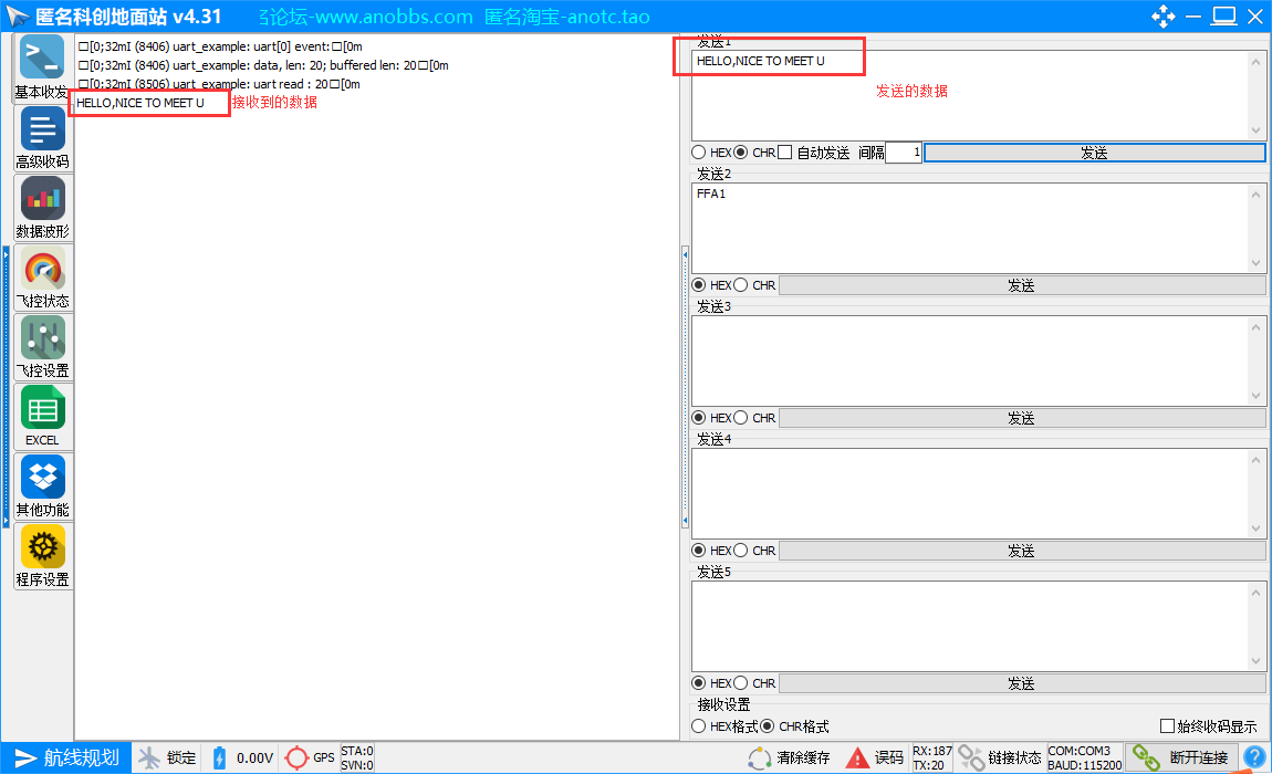
由于本人手上没有硬件流相关的串口调试器,所以对于uart1的验证无法进行了,这里只对uart0的结果进行实验。
打开串口调试助手,连接esp32(通过usb直接连接即可),发送数据,可以得到如下结果。说明串口数据发送成功。
