本文档介绍,如何修改和控制 S5M8767,以 camera 扩展端子的 VDD28_AF,VDD28_CAM 为例,来具体介绍驱动中如何实现电源修改和控制。
另外还有一个文档“iTOP-4412-驱动-电源管理芯片修改输出电压”,用户可以在技术支持群中搜到,其中涉及到具体结构的分析,也很有参考价值。
本文档以具体的驱动小例程介绍在已经配置好的源码中做修改,用户可以将其集成到自己的驱动中,也提供了驱动测试例程压缩包“power_s5m8767a.tar.gz”。
1. 硬件分析
1.1 原理图分析
如下图所示,在底板原理图中找到 camera 扩展端子,这里以 VDD28_AF,VDD28_CAM 为例。camera 摄像头驱动中需要将其设置为 2.8v 的电压,后面我们将其修改为 3.3v 输出(需要去掉 camera 摄像头驱动)。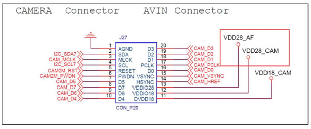
如下图所示,核心板原理图中搜索网络“VDD28_AF”和“VDD28_CAM”。可以看到“VDD28_AF”和“VDD28_CAM”分别对应电源芯片 S5M8767A 的“VLDO20”和“VLDO21”。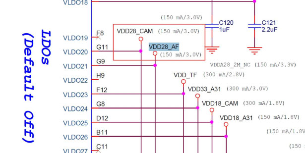
1.2 电源芯片 S5M8767A 的 datasheet 分析
S5M8767A 的 datasheet 的 2.3.1 小节,如下图所示。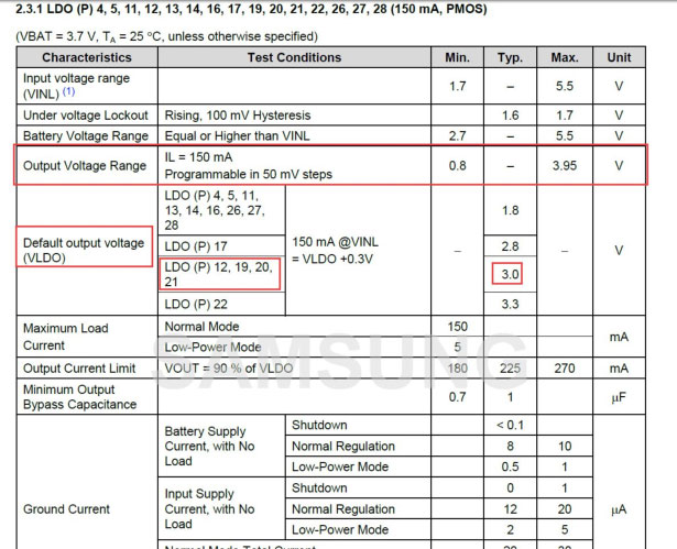
如上图所示,注意红框中的内容。最上面的红框中,表示输出的电流是 150mA,最低输出电压是 0.8v,最大电压是 3.95v。下面红框中,介绍的是默认输出电压,可以看到 LDO20和 LDO21,默认输出的是 3.0v。
2. 软件
如果要改变输出电压,可以通过修改平台文件实现;在驱动中,可以通过函数调用,控制电源输出。
通过前面的分析可知,ldo21 和 ldo20 输出电流范围是 0.8v 到 3.95v。
2.1 平台文件修改输出电压
在内核的“arch/arm/mach-exynos/mach-itop4412.c”文件中,如下图所示进行修改。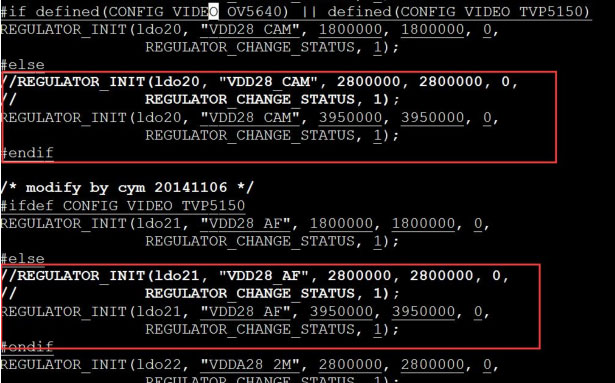
将REGULATOR_INIT(ldo20, "VDD28_CAM", 2800000, 2800000, 0,REGULATOR_CHANGE_STATUS, 1);
注释掉,修改为 2800000,为 3950000(函数 REGULATOR_INIT 中的第一个参数表示8767 电源芯片的第 20 路,第三个参数表示输出最低电压,第四个参数表示输出最高电压)。这里设置为最低和最高全部为 3.95v。同理,我们将第 21 路也修改为 3950000,如上图所示。
接着在 menuconfig 中,将 ov5640 摄像头的驱动去掉,因为在摄像头中会初始化和配置。ov5640 摄像头摄像头的配置路径如下图所示。下面截图是已经去掉的截图,默认缺省文件是配置上的。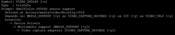
2.2 驱动例程
驱动例程“power_s5m8767a.tar.gz”和文档在同一压缩包中。
编写一个简单的驱动测试程序,源码如下所示。
#include
#include
#include
#include
#include
#include
#include
#include
#include
#include
#include
#include
struct regulator *ov_vddaf_cam_regulator = NULL;
struct regulator *ov_vdd5m_cam_regulator = NULL;
struct regulator *ov_vdd18_cam_regulator = NULL;
struct regulator *ov_vdd28_cam_regulator = NULL;
MODULE_LICENSE("Dual BSD/GPL");
MODULE_AUTHOR("iTOPEET_dz");
static int power(int flag)
{
if(1 == flag){
regulator_enable(ov_vdd18_cam_regulator);
udelay(10);
regulator_enable(ov_vdd28_cam_regulator);
udelay(10);
regulator_enable(ov_vdd5m_cam_regulator); //DOVDD DVDD 1.8v
udelay(10);
regulator_enable(ov_vddaf_cam_regulator); //AVDD 2.8v
udelay(10);
}
else if(0 == flag){
regulator_disable(ov_vdd18_cam_regulator);
udelay(10);
regulator_disable(ov_vdd28_cam_regulator);
udelay(10);
regulator_disable(ov_vdd5m_cam_regulator);
udelay(10);
regulator_disable(ov_vddaf_cam_regulator);
udelay(10);
}
return 0 ;
}
static void power_init(void)
{
int ret;
ov_vdd18_cam_regulator = regulator_get(NULL, "vdd18_cam");
if (IS_ERR(ov_vdd18_cam_regulator)) {
printk("%s: failed to get %s
", __func__, "vdd18_cam");
ret = -ENODEV;
goto err_regulator;
}
ov_vdd28_cam_regulator = regulator_get(NULL, "vdda28_2m");
if (IS_ERR(ov_vdd28_cam_regulator)) {
printk("%s: failed to get %s
", __func__, "vdda28_2m");
ret = -ENODEV;
goto err_regulator;
}
ov_vddaf_cam_regulator = regulator_get(NULL, "vdd28_af");
if (IS_ERR(ov_vddaf_cam_regulator)) {
printk("%s: failed to get %s
", __func__, "vdd28_af");
ret = -ENODEV;
goto err_regulator;
}
ov_vdd5m_cam_regulator = regulator_get(NULL, "vdd28_cam");
if (IS_ERR(ov_vdd5m_cam_regulator)) {
printk("%s: failed to get %s
", __func__, "vdd28_cam");
ret = -ENODEV;
goto err_regulator;
}
err_regulator:
regulator_put(ov_vddaf_cam_regulator);
regulator_put(ov_vdd5m_cam_regulator);
regulator_put(ov_vdd18_cam_regulator);
regulator_put(ov_vdd28_cam_regulator);
}
static int hello_init(void)
{
power_init();
power(1);
printk(KERN_EMERG "Hello World enter!
");
return 0;
}
static void hello_exit(void)
{
power(0);
printk(KERN_EMERG "Hello world exit!
");
}
module_init(hello_init);
module_exit(hello_exit);
Makefile 如下所示。
#!/bin/bash
obj-m += power_s5m8767a_test.o
KDIR := /home/topeet/android4.0/iTop4412_Kernel_3.0
PWD ?= $(shell pwd)
all:
make -C $(KDIR) M=$(PWD) modules
clean:
rm -rf *.o modules.order *.ko *mod.c Module.symvers
使用 make 命令编译驱动模块,如下图所示。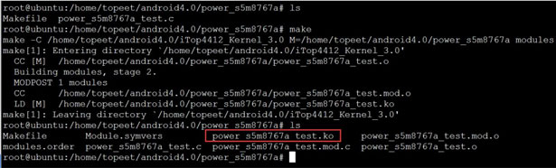
3. 测试
如下图所示,加载驱动之后,测量电压大约为 2.85 左右(有压降),卸载驱动之后,电
压为 0。说明驱动运行成功,用户在自己的项目中,假如需要用到电源控制,可以参考本例程
来实现。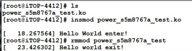
对于初学者来说,选择一款合适的开发板非常重要!
迅为给出了明确的学习路线,首先,你需要研读一下这个视频教程:
嵌入式学习方法篇:https://www.bilibili.com/video/BV1HE411w7by?p=1
然后,需要学习一下Linux的系统框架: https://www.bilibili.com/video/BV1HE411w7by?p=2
接下来可以做一些实践了,比如编译系统的安装、编译以及烧写;这些可以按照迅为的视频教程来学习,也可以参考多达2300页的用户使用手册。
入门篇:https://www.bilibili.com/video/B ... 7086078002054549963
另外,迅为提供了广受赞誉的QT入门教程:
QT学习篇:https://www.bilibili.com/video/B ... 7086078002054549963
接下来可以学习一下驱动相关技术:
Linux驱动专题:https://www.bilibili.com/video/B ... 2661886997282795316
再往下是非常接地气的实战教程:
机车导航项目:https://www.bilibili.com/video/B ... 7086078002054549963
云服务器智能家居:https://www.bilibili.com/video/B ... 7086078002054549963
按这样的路线图学下来,在迅为强大售后的帮助下,相信你很快跨入嵌入式开发的大门!