A monitor draws an image on the screen by using an electron beam (3 electron beams for color models, 1 electron beam for monochrome monitors). The front of the screen is covered by a pattern of colored phosphors (pixels). If a phosphor is hit by an electron, it emits a photon and thus becomes visible.
The electron beam draws horizontal lines (scanlines) from left to right, and from the top to the bottom of the screen. By modifying the intensity of the electron beam, pixels with various colors and intensities can be shown.
After each scanline the electron beam has to move back to the left side of the screen and to the next line: this is called the horizontal retrace. After the whole screen (frame) was painted, the beam moves back to the upper left corner: this is called the vertical retrace. During both the horizontal and vertical retrace, the electron beam is turned off (blanked).
The speed at which the electron beam paints the pixels is determined by the dotclock in the graphics board. For a dotclock of e.g. 28.37516 MHz (millions of cycles per second), each pixel is 35242 ps (picoseconds) long:
1/(28.37516E6 Hz) = 35.242E-9 s
If the screen resolution is 640x480, it will take
640*35.242E-9 s = 22.555E-6 s
to paint the 640 (xres) pixels on one scanline. But the horizontal retrace also takes time (e.g. 272 `pixels'), so a full scanline takes
(640+272)*35.242E-9 s = 32.141E-6 s
We'll say that the horizontal scanrate is about 31 kHz:
1/(32.141E-6 s) = 31.113E3 Hz
A full screen counts 480 (yres) lines, but we have to consider the vertical retrace too (e.g. 49 `lines'). So a full screen will take
(480+49)*32.141E-6 s = 17.002E-3 s
The vertical scanrate is about 59 Hz:
1/(17.002E-3 s) = 58.815 Hz
This means the screen data is refreshed about 59 times per second. To have a stable picture without visible flicker, VESA recommends a vertical scanrate of at least 72 Hz. But the perceived flicker is very human dependent: some people can use 50 Hz without any trouble, while I'll notice if it's less than 80 Hz.
Since the monitor doesn't know when a new scanline starts, the graphics board will supply a synchronization pulse (horizontal sync or hsync) for each scanline. Similarly it supplies a synchronization pulse (vertical sync or vsync) for each new frame. The position of the image on the screen is influenced by the moments at which the synchronization pulses occur.
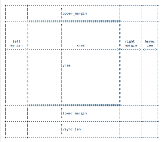
The following picture summarizes all timings. The horizontal retrace time is the sum of the left margin, the right margin and the hsync length, while the vertical retrace time is the sum of the upper margin, the lower margin and the vsync length.

The frame buffer device expects all horizontal timings in number of dotclocks (in picoseconds, 1E-12 s), and vertical timings in number of scanlines.
6. Converting XFree86 timing values info frame buffer device timings
--------------------------------------------------------------------
An XFree86 mode line consists of the following fields:
"800x600" 50 800 856 976 1040 600 637 643 666
< name > DCF HR SH1 SH2 HFL VR SV1 SV2 VFL
The frame buffer device uses the following fields:
- pixclock: pixel clock in ps (pico seconds)
- left_margin: time from sync to picture
- right_margin: time from picture to sync
- upper_margin: time from sync to picture
- lower_margin: time from picture to sync
- hsync_len: length of horizontal sync
- vsync_len: length of vertical sync
1) Pixelclock: xfree: in MHz
fb: in picoseconds (ps)
pixclock = 1000000 / DCF
2) horizontal timings: left_margin = HFL - SH2
right_margin = SH1 - HR
hsync_len = SH2 - SH1
3) vertical timings:
upper_margin = VFL - SV2
lower_margin = SV1 - VR
vsync_len = SV2 - SV1
Good examples for VESA timings can be found in the XFree86 source tree, under "xc/programs/Xserver/hw/xfree86/doc/modeDB.txt".