概述:
ESP32-WROOM-32 是一款通用型 Wi-Fi+BT+BLE MCU 模组,功能强大,用途广泛,可以用于低功耗传感器网
络和要求极高的任务,例如语音编码、音频流和 MP3 解码等。
此款模组的核心是 ESP32-D0WDQ6 芯片 *,具有可扩展、自适应的特点。两个 CPU 核可以被单独控制。时钟
频率的调节范围为 80 MHz 到 240 MHz。用户可以切断 CPU 的电源,利用低功耗协处理器来不断地监测外设
的状态变化或某些模拟量是否超出阈值。 ESP32 还集成了丰富的外设,包括电容式触摸传感器、霍尔传感器、
低噪声传感放大器, SD 卡接口、以太网接口、高速 SDIO/SPI、 UART、 I2S 和 I2C 等。
模组集成了传统蓝牙、低功耗蓝牙和 Wi-Fi,具有广泛的用途: Wi-Fi 支持极大范围的通信连接,也支持通过路
由器直接连接互联网;而蓝牙可以让用户连接手机或者广播 BLE Beacon 以便于信号检测。 ESP32 芯片的睡眠
电流小于 5 µA,使其适用于电池供电的可穿戴电子设备。模组支持的数据传输速率高达 150 Mbps,天线输出
功率达到 20 dBm,可实现最大范围的无线通信。因此,这款模组具有行业领先的技术规格,在高集成度、无线
传输距离、功耗以及网络联通等方面性能极佳。
ESP32 的操作系统是带有 LwIP 的 freeRTOS,还内置了带有硬件加速功能的 TLS 1.2。芯片同时支持 OTA 加密
升级,方便用户在产品发布之后继续升级。
ESP32启动后跑的是一个freeRTOS操作系统,最终跑到main.app函数
本文将会介绍 ESP32 从上电到运行 app_main 函数中间所经历的步骤(即启动流程):
Application startup flow

This note explains various steps which happen before app_main function of an ESP-IDF application is called.

The high level view of startup process is as follows:

    First-stage bootloader in ROM loads second-stage bootloader image to RAM (IRAM & DRAM) from flash offset 0x1000.
    Second-stage bootloader loads partition table and main app image from flash. Main app incorporates both RAM segments and read-only segments mapped via flash cache.
    Main app image executes. At this point the second CPU and RTOS scheduler can be started.

This process is explained in detail in the following sections.
First stage bootloader

After SoC reset, PRO CPU will start running immediately, executing reset vector code, while APP CPU will be held in reset. During startup process, PRO CPU does all the initialization. APP CPU reset is de-asserted in the call_start_cpu0 function of application startup code. Reset vector code is located at address 0x40000400 in the mask ROM of the {IDF_TARGET_NAME} chip and can not be modified.

Startup code called from the reset vector determines the boot mode by checking GPIO_STRAP_REG register for bootstrap pin states. Depending on the reset reason, the following takes place:

    Reset from deep sleep: if the value in RTC_CNTL_STORE6_REG is non-zero, and CRC value of RTC memory in RTC_CNTL_STORE7_REG is valid, use RTC_CNTL_STORE6_REG as an entry point address and jump immediately to it. If RTC_CNTL_STORE6_REG is zero, or RTC_CNTL_STORE7_REG contains invalid CRC, or once the code called via RTC_CNTL_STORE6_REG returns, proceed with boot as if it was a power-on reset. Note: to run customized code at this point, a deep sleep stub mechanism is provided. Please see :doc:`deep sleep <deep-sleep-stub>` documentation for this.
    For power-on reset, software SOC reset, and watchdog SOC reset: check the GPIO_STRAP_REG register if UART or SDIO download mode is requested. If this is the case, configure UART or SDIO, and wait for code to be downloaded. Otherwise, proceed with boot as if it was due to software CPU reset.
    For software CPU reset and watchdog CPU reset: configure SPI flash based on EFUSE values, and attempt to load the code from flash. This step is described in more detail in the next paragraphs. If loading code from flash fails, unpack BASIC interpreter into the RAM and start it. Note that RTC watchdog is still enabled when this happens, so unless any input is received by the interpreter, watchdog will reset the SOC in a few hundred milliseconds, repeating the whole process. If the interpreter receives any input from the UART, it disables the watchdog.

Application binary image is loaded from flash starting at address 0x1000. First 4kB sector of flash is used to store secure boot IV and signature of the application image. Please check secure boot documentation for details about this.
Second stage bootloader

In ESP-IDF, the binary image which resides at offset 0x1000 in flash is the second stage bootloader. Second stage bootloader source code is available in components/bootloader directory of ESP-IDF. Note that this arrangement is not the only one possible with the {IDF_TARGET_NAME} chip. It is possible to write a fully featured application which would work when flashed to offset 0x1000, but this is out of scope of this document. Second stage bootloader is used in ESP-IDF to add flexibility to flash layout (using partition tables), and allow for various flows associated with flash encryption, secure boot, and over-the-air updates (OTA) to take place.

When the first stage bootloader is finished checking and loading the second stage bootloader, it jumps to the second stage bootloader entry point found in the binary image header.

Second stage bootloader reads the partition table found at offset 0x8000. See :doc:`partition tables <partition-tables>` documentation for more information. The bootloader finds factory and OTA partitions, and decides which one to boot based on data found in OTA info partition.

For the selected partition, second stage bootloader copies data and code sections which are mapped into IRAM and DRAM to their load addresses. For sections which have load addresses in DROM and IROM regions, flash MMU is configured to provide the correct mapping. Note that the second stage bootloader configures flash MMU for both PRO and APP CPUs, but it only enables flash MMU for PRO CPU. Reason for this is that second stage bootloader code is loaded into the memory region used by APP CPU cache. The duty of enabling cache for APP CPU is passed on to the application. Once code is loaded and flash MMU is set up, second stage bootloader jumps to the application entry point found in the binary image header.

Currently it is not possible to add application-defined hooks to the bootloader to customize application partition selection logic. This may be required to load different application image depending on a state of a GPIO, for example. Such customization features will be added to ESP-IDF in the future. For now, bootloader can be customized by copying bootloader component into application directory and making necessary changes there. ESP-IDF build system will compile the component in application directory instead of ESP-IDF components directory in this case.
Application startup

ESP-IDF application entry point is call_start_cpu0 function found in components/{IDF_TARGET_PATH_NAME}/cpu_start.c. Two main things this function does are to enable heap allocator and to make APP CPU jump to its entry point, call_start_cpu1. The code on PRO CPU sets the entry point for APP CPU, de-asserts APP CPU reset, and waits for a global flag to be set by the code running on APP CPU, indicating that it has started. Once this is done, PRO CPU jumps to start_cpu0 function, and APP CPU jumps to start_cpu1 function.

Both start_cpu0 and start_cpu1 are weak functions, meaning that they can be overridden in the application, if some application-specific change to initialization sequence is needed. Default implementation of start_cpu0 enables or initializes components depending on choices made in menuconfig. Please see source code of this function in components/{IDF_TARGET_PATH_NAME}/cpu_start.c for an up to date list of steps performed. Note that any C++ global constructors present in the application will be called at this stage. Once all essential components are initialized, main task is created and FreeRTOS scheduler is started.

While PRO CPU does initialization in start_cpu0 function, APP CPU spins in start_cpu1 function, waiting for the scheduler to be started on the PRO CPU. Once the scheduler is started on the PRO CPU, code on the APP CPU starts the scheduler as well.

Main task is the task which runs app_main function. Main task stack size and priority can be configured in menuconfig. Application can use this task for initial application-specific setup, for example to launch other tasks. Application can also use main task for event loops and other general purpose activities. If app_main function returns, main task is deleted.
Application memory layout

{IDF_TARGET_NAME} chip has flexible memory mapping features. This section describes how ESP-IDF uses these features by default.

Application code in ESP-IDF can be placed into one of the following memory regions.
IRAM (instruction RAM)

ESP-IDF allocates part of Internal SRAM0 region (defined in the Technical Reference Manual) for instruction RAM. Except for the first 64 kB block which is used for PRO and APP CPU caches, the rest of this memory range (i.e. from 0x40080000 to 0x400A0000) is used to store parts of application which need to run from RAM.

A few components of ESP-IDF and parts of WiFi stack are placed into this region using the linker script.

If some application code needs to be placed into IRAM, it can be done using IRAM_ATTR define:

#include "esp_attr.h"

void IRAM_ATTR gpio_isr_handler(void* arg)
{
        // ...
}

Here are the cases when parts of application may or should be placed into IRAM.

    Interrupt handlers must be placed into IRAM if ESP_INTR_FLAG_IRAM is used when registering the interrupt handler. In this case, ISR may only call functions placed into IRAM or functions present in ROM. Note 1: all FreeRTOS APIs are currently placed into IRAM, so are safe to call from interrupt handlers. If the ISR is placed into IRAM, all constant data used by the ISR and functions called from ISR (including, but not limited to, const char arrays), must be placed into DRAM using DRAM_ATTR.
    Some timing critical code may be placed into IRAM to reduce the penalty associated with loading the code from flash. {IDF_TARGET_NAME} reads code and data from flash via a 32 kB cache. In some cases, placing a function into IRAM may reduce delays caused by a cache miss.

IROM (code executed from Flash)

If a function is not explicitly placed into IRAM or RTC memory, it is placed into flash. The mechanism by which Flash MMU is used to allow code execution from flash is described in the Technical Reference Manual. ESP-IDF places the code which should be executed from flash starting from the beginning of 0x400D0000 — 0x40400000 region. Upon startup, second stage bootloader initializes Flash MMU to map the location in flash where code is located into the beginning of this region. Access to this region is transparently cached using two 32kB blocks in 0x40070000 — 0x40080000 range.

Note that the code outside 0x40000000 — 0x40400000 region may not be reachable with Window ABI CALLx instructions, so special care is required if 0x40400000 — 0x40800000 or 0x40800000 — 0x40C00000 regions are used by the application. ESP-IDF doesn't use these regions by default.
RTC fast memory

The code which has to run after wake-up from deep sleep mode has to be placed into RTC memory. Please check detailed description in :doc:`deep sleep <deep-sleep-stub>` documentation.
DRAM (data RAM)

Non-constant static data and zero-initialized data is placed by the linker into the 256 kB 0x3FFB0000 — 0x3FFF0000 region. Note that this region is reduced by 64kB (by shifting start address to 0x3FFC0000) if Bluetooth stack is used. Length of this region is also reduced by 16 kB or 32kB if trace memory is used. All space which is left in this region after placing static data there is used for the runtime heap.

Constant data may also be placed into DRAM, for example if it is used in an ISR (see notes in IRAM section above). To do that, DRAM_ATTR define can be used:

DRAM_ATTR const char[] format_string = "%p %x";
char buffer[64];
sprintf(buffer, format_string, ptr, val);

Needless to say, it is not advised to use printf and other output functions in ISRs. For debugging purposes, use ESP_EARLY_LOGx macros when logging from ISRs. Make sure that both TAG and format string are placed into DRAM in that case.

The macro __NOINIT_ATTR can be used as attribute to place data into .noinit section. The values placed into this section will not be initialized at startup and keep its value after software restart.

Example:

__NOINIT_ATTR uint32_t noinit_data;

DROM (data stored in Flash)

By default, constant data is placed by the linker into a 4 MB region (0x3F400000 — 0x3F800000) which is used to access external flash memory via Flash MMU and cache. Exceptions to this are literal constants which are embedded by the compiler into application code.
RTC slow memory

Global and static variables used by code which runs from RTC memory (i.e. deep sleep stub code) must be placed into RTC slow memory. Please check detailed description in :doc:`deep sleep <deep-sleep-stub>` documentation.

The attribute macro named RTC_NOINIT_ATTR can be used to place data into this type of memory. The values placed into this section keep their value after waking from deep sleep.

Example:

RTC_NOINIT_ATTR uint32_t rtc_noinit_data;

DMA Capable Requirement

Most DMA controllers (e.g. SPI, sdmmc, etc.) have requirements that sending/receiving buffers should be placed in DRAM and word-aligned. We suggest to place DMA buffers in static variables rather than in the stack. Use macro DMA_ATTR to declare global/local static variables like:

DMA_ATTR uint8_t buffer[]="I want to send something";

void app_main()
{
    // initialization code...
    spi_transaction_t temp = {
        .tx_buffer = buffer,
        .length = 8*sizeof(buffer),
    };
    spi_device_transmit( spi, &temp );
    // other stuff
}

Or:

void app_main()
{
    DMA_ATTR static uint8_t buffer[]="I want to send something";
    // initialization code...
    spi_transaction_t temp = {
        .tx_buffer = buffer,
        .length = 8*sizeof(buffer),
    };
    spi_device_transmit( spi, &temp );
    // other stuff
}

Placing DMA buffers in the stack is still allowed, though you have to keep in mind:

    Never try to do this if the stack is in the pSRAM. If the stack of a task is placed in the pSRAM, several steps have to be taken as described in :doc:`external-ram` (at least SPIRAM_ALLOW_STACK_EXTERNAL_MEMORY option enabled in the menuconfig). Make sure your task is not in the pSRAM.

    Use macro WORD_ALIGNED_ATTR in functions before variables to place them in proper positions like:

    void app_main()
    {
        uint8_t stuff;
        WORD_ALIGNED_ATTR uint8_t buffer[]="I want to send something";   //or the buffer will be placed right after stuff.
        // initialization code...
        spi_transaction_t temp = {
            .tx_buffer = buffer,
            .length = 8*sizeof(buffer),
        };
        spi_device_transmit( spi, &temp );
        // other stuff
    }
相关函数与库可在arduino-esp32\esp32(开发工具包)下面的cores与libraries文件下找,但是libraries文件下的库文件如果程序没有包含,是没办法使用里面的源文件的。cores文件下内容是默认被编译进去的。
自己下载的库可以放在project路径下的libraries文件夹里,编译时一样能找到
main.app函数在cores文件下,main.app里面就有setup函数与loop函数,即可明白代码setup函数与loop函数作用
贴上main.app的源代码:
#include "freertos/FreeRTOS.h"
#include "freertos/task.h"
#include "Arduino.h"

#if CONFIG_AUTOSTART_ARDUINO

#if CONFIG_FREERTOS_UNICORE
#define ARDUINO_RUNNING_CORE 0
#else
#define ARDUINO_RUNNING_CORE 1
#endif

void loopTask(void *pvParameters)
{
    setup();
    for(;;) {
        micros(); //update overflow
        loop();
    }
}

extern "C" void app_main()
{
    initArduino();
    xTaskCreatePinnedToCore(loopTask, "loopTask", 8192, NULL, 1, NULL, ARDUINO_RUNNING_CORE);
}

#endif
arduino支持c++,所以可以使用c++进行编程
环境搭建:
先安装arduino-1.8.4-windows(路径最好不要有中文)(比如路径F:\Arduino)这款软件是免费的
安装好后把esp32的开发工具包解压到Arduino安装目录\hardware下,文件路径各内容为:
hardware下:arduino-esp32--master文件夹
arduino-esp32--master下:esp32文件夹
esp32下:esp32的开发工具包相关文件
esp32开发工具包可以在这个网址下载:https://github.com/espressif/arduino-esp32
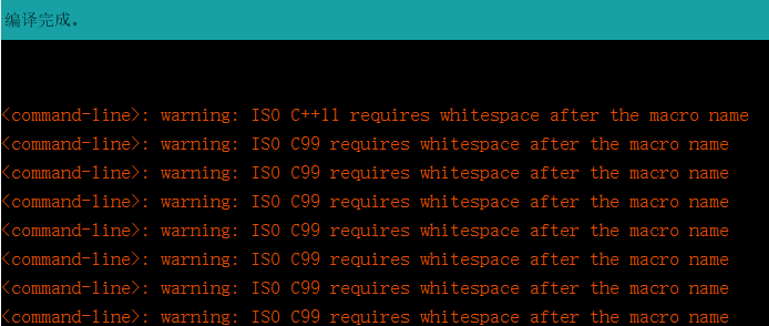
坑1:
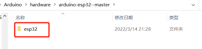
这个文件名的是esp32,不然会报以下警告,原因未知:
坑2:
工程编译时出现这个警告:
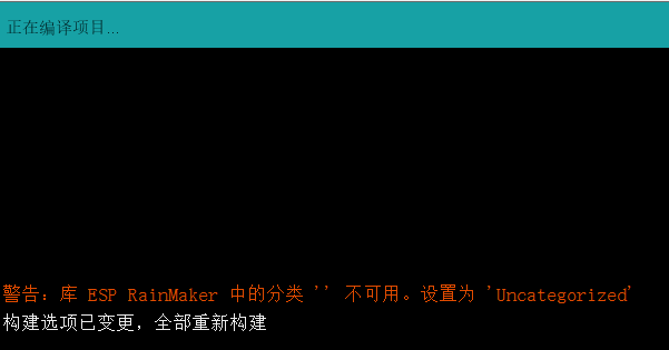
这个就是该库里面的library.properties文件“分类”这个参数没有,我们要按照它的要求添加。
如图所示:
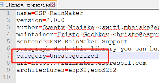
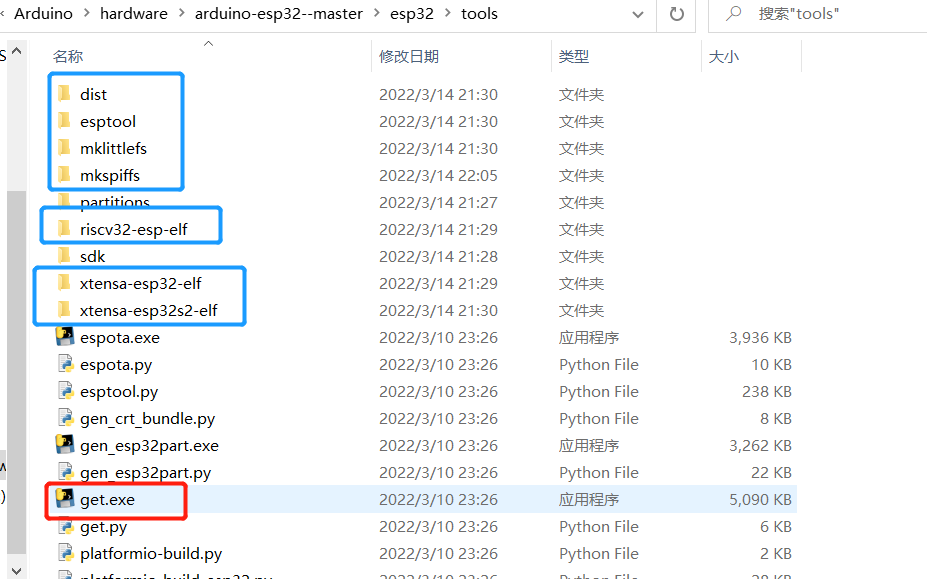
复制进去之后,在如图所示路径找到get.exe,文件,然后双击运行以下,这个程序就会下载一些文件(此处需要science上网),如图蓝色方框所示,应该是es32的一些编译软件吧。
安装好后点开桌面的Arduino软件
界面设置:
工具-----开发板-----esp32 dev module(用哪款就选哪款,我用的是esp32,所以选择这一款)(导入esp32的开发工具包之后可以看到)
工具-----端口-------勾选(选择开发板连接的串口,用于下载程序等)
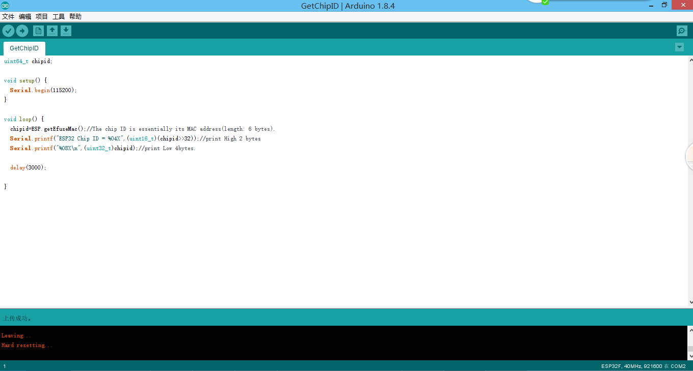
文件-----示例-------ESP32-----chipID-----GetChipID(示例程序,获取开发板ESP32 ID 并打印到串口上,一般波特率为115200,8位数据,1位停止,无校验位)
flsh frequency:80mhz
unload speed:921600
编译器:avrisp mkll
其他的默认即可,如图所示:

插上ESP32开发板;
在GetChipID界面点击上传,界面底部显示上传成功表示程序下载成功
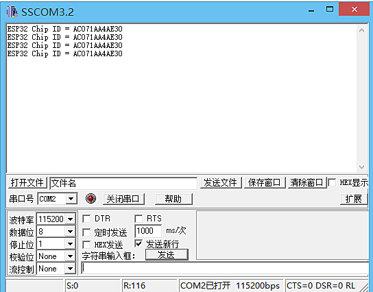
接着打开SSCON32串口调试软件,选择串口号-----打开串口
如果开发板正常会自动发送ID号
测试成功图片:
下载成功图片
******************************************************************************
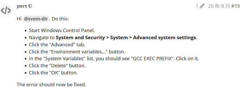
当编译时出现xtensa-esp32-elf-g++: error: CreateProcess: No such file or directory错误时,参考一下解决方案:
参考https://forum.arduino.cc/t/avr-g-error-device-specs-specs-atmega328p-no-such-file-or-directory/569829 15楼回答
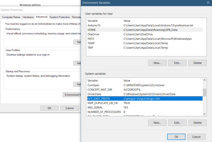
如果软件版本太低也可能,我之前是1.8.4版本,经常报这个错误,感觉是不怎么兼容,换成1.8.19后就可以啦
****************************************************************************