2020-05-31 17:41:09
TMS320F28335 想实现设定ADC采样频率,通过设置 ADC_CKPS 和 ADC_SHCLK 分频系数是可以在一定范围内改变ADC采样频率的,但是只调节分频系数时,ADC采样频率最低只能到十几KHz: 28335 ADC 对100Hz方波采样,于是问题变得复杂了一些。
参考了有相同需求的帖子:28335的ADC采样频率如何设置? 、DSP28335中如何设置ADC采样的频率?
得出结论:若想把ADC采样频率降低到一定水平(如1000Hz、2000Hz等),仅改变ADC分频系数是不够的,还需利用ePWM来生成ADC的启停信号,使其作为ADC的开关,释放启停信号来控制ADC,进而改变ADC的采样频率可调,而ePWM的频率就是ADC启停频率,
于是我们现在关心ePWM的频率/周期设置:
ePWM的寄存器主要有7个,我们这里重点关注:时基周期寄存器TBPRD和时基计数器模式:

于是,决定Tpwm的变量有计算公式、TBPRD和TBCLK:
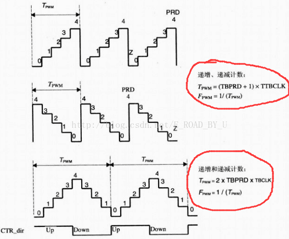
(1).计算公式:不同计数模式的计算公式不同,从图中看出:
在增减计数模式下,Tpwm = (TBPRD+1) x TBCLK ;
在递增和递减计数模式下,Tpwm = 2 x TBPRD x TBCLK ;
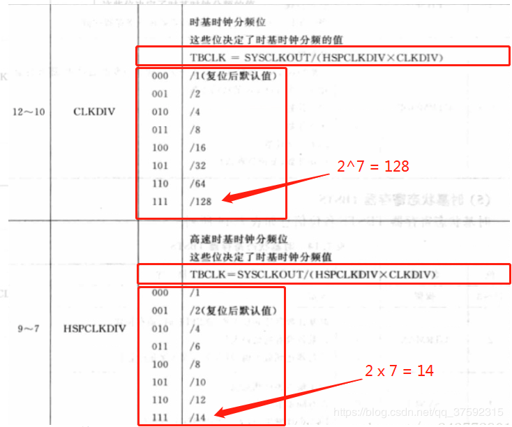
(2).TBCLK = SYSCLKOUT / ( (2*HSPCLKDIV) * (2^CLKDIV) );
TBCLK由 SYSCLKOUT、HSPCLKDIV和CLKDIV决定,这里28335的SYSCLKOUT默认150MHz,查表后得知:代码中 CLKDIV = n ,公式中变为:CLKDIV = 2^n ;在程序中 HSPCLKDIV = n,公式中 HSPCLKDIV = 2n ;
(3).TBPRD:按照公式(不同计数模式的Tpwm公式不同)计算得出数,手动填入,例如要把PWM的频率、(即ADC的采样频率)设置为2000Hz:
1 // Set Period for EPWM1
2 // up-and-down count mode:
3 // Tpwm = 2*(1/TBCLK)*TBPRD;
4
5 // up-count mode or down-count mode:( use this mode here )
6 // Tpwm = (1/TBCLK)*(1+TBPRD);
7     EPwm1Regs.TBPRD = (12500-1); // max = 65536
8  // Setup  T(PWM1)=(1/TBCLK)*(1+TBPRD)=(1/25000000)*(1+12500-1)=0.0005s ,F(PWM1) = 1/T(PWM1) = 1/0.0005s = 2000Hz
完整的可用ADC.c代码如下:
  1 #include "DSP2833x_Device.h"     // DSP2833x Headerfile Include File
  2 #include "DSP2833x_Examples.h"   // DSP2833x Examples Include File
  3 #include "math.h"
  4 #include "DSP2833x_Project.h"
  5 #include "DSP2833x_EPwm.h"
  6 #include "DSP2833x_EPwm_defines.h"
  7 // lower sample rate to 2KHz using ePWM interrupt
  8 // as well as turn on 2 channels
  9
 10 // Determine when the shift to right justify the data takes place
 11 // Only one of these should be defined as 1.
 12 // The other two should be defined as 0.
 13 #define POST_SHIFT   0  // Shift results after the entire sample table is full
 14 #define INLINE_SHIFT 1  // Shift results as the data is taken from the results regsiter
 15 #define NO_SHIFT     0  // Do not shift the results
 16
 17 #define BUF_SIZE   512  // Sample buffer size
 18
 19     // Prototype statements for functions found within this file.
 20     interrupt void adc_isr(void);
 21
 22     // Global variables used in this example:
 23     Uint16 LoopCount_1;
 24     Uint16 LoopCount_2;
 25     Uint16 ConversionCount;
 26
 27     Uint16 SampleTable_1[BUF_SIZE]={0};
 28     Uint16 SampleTable_2[BUF_SIZE]={0};
 29
 30
 31     main()
 32     {
 33
 34     // Initialize System Control:
 35     // PLL, WatchDog, enable Peripheral Clocks
 36     // This example function is found in the DSP2833x_SysCtrl.c file.
 37     InitSysCtrl();
 38
 39     EALLOW;
 40     #if (CPU_FRQ_150MHZ) // Default - 150 MHz SYSCLKOUT
 41     #define ADC_MODCLK 0x3 // HSPCLK = SYSCLKOUT/2*ADC_MODCLK2 = 150/(2*3) = 25.0 MHz
 42     #endif
 43     #if (CPU_FRQ_100MHZ)
 44     #define ADC_MODCLK 0x2 // HSPCLK = SYSCLKOUT/2*ADC_MODCLK2 = 100/(2*2) = 25.0 MHz
 45     #endif
 46     EDIS;
 47     // Clear all interrupts and initialize PIE vector table:
 48     // Disable CPU interrupts
 49     DINT;
 50
 51     // Initialize the PIE control registers to their default state.
 52     // The default state is all PIE interrupts disabled and flags are cleared.
 53     // This function is found in the DSP2833x_PieCtrl.c file.
 54     InitPieCtrl();
 55
 56     EALLOW;
 57     SysCtrlRegs.HISPCP.all = ADC_MODCLK;                       // set ADC CLOCK ,HSPCLK = SYSCLKOUT/ADC_MODCLK
 58     EDIS;
 59
 60     // Disable CPU interrupts and clear all CPU interrupt flags:
 61     IER = 0x0000;
 62     IFR = 0x0000;
 63
 64     // Initialize the PIE vector table with pointers to the shell Interrupt
 65     // Service Routines (ISR).
 66     // This will populate the entire table, even if the interrupt
 67     // is not used in this example. This is useful for debug purposes.
 68     // The shell ISR routines are found in DSP2833x_DefaultIsr.c.
 69     // This function is found in DSP2833x_PieVect.c.
 70     InitPieVectTable();
 71
 72     // Interrupts that are used in this example are re-mapped to
 73     // ISR functions found within this file.
 74     EALLOW; // This is needed to write to EALLOW protected register
 75     PieVectTable.ADCINT = &adc_isr;
 76     EDIS;                                                                                           // This is needed to disable write to EALLOW protected registers
 77
 78     InitAdc();                                                                                     // For this example, init the ADC
 79
 80     // Enable ADCINT in PIE
 81     PieCtrlRegs.PIEIER1.bit.INTx6 = 1;
 82     IER |= M_INT1;                                                                             // Enable CPU Interrupt 1
 83     EINT;                                                                                             // Enable Global interrupt INTM
 84     ERTM;                                                                                             // Enable Global realtime interrupt DBGM
 85
 86     LoopCount_1 = 0;
 87     LoopCount_2 = 0;
 88     ConversionCount = 0;
 89
 90     // Configure ADC
 91     ///////////////////////设置最大通道数:2/////////////////////////////
 92     AdcRegs.ADCMAXCONV.all = 0x0001;                                         // Setup 2 conv's on SEQ1
 93     AdcRegs.ADCCHSELSEQ1.bit.CONV00 = 0x0;                             // Setup ADCINA3 as 1st SEQ1 conv.
 94     AdcRegs.ADCCHSELSEQ1.bit.CONV01 = 0x1;                             // Setup ADCINA2 as 2nd SEQ1 conv.
 95     //////////////////////////////////////////////////////////////////////
 96     AdcRegs.ADCTRL2.bit.EPWM_SOCA_SEQ1 = 1;                            // Enable SOCA from ePWM to start SEQ1
 97     AdcRegs.ADCTRL2.bit.INT_ENA_SEQ1 = 1;                             // Enable SEQ1 interrupt (every EOS)
 98
 99     // Assumes ePWM1 clock is already enabled in InitSysCtrl();
100     EPwm1Regs.ETSEL.bit.SOCAEN = 1;                                         // Enable SOC on A group
101     EPwm1Regs.ETSEL.bit.SOCASEL = 4;                                         // Select SOC from from CPMA on upcount
102     EPwm1Regs.ETPS.bit.SOCAPRD = 1;                                         // Generate pulse on 1st event
103     EPwm1Regs.CMPA.half.CMPA = 0x0080;                                     // Set compare A value
104     EPwm1Regs.TBCTL.bit.CTRMODE = 0;                                         // 0 -- count up and start
105
106 ///////////////配置ePWM中断频率,即设置ADC采样频率////////////////
107 // High Speed Time-base Clock Prescale Bits,These bits determine part of the time-base clock prescale
108 // SYSCLKOUT = 150MHz
109 // TBCLK = SYSCLKOUT / ( (2*HSPCLKDIV) * (2^CLKDIV) )=150MHz/(2*3*1)=25MHz
110    EPwm1Regs.TBCTL.bit.HSPCLKDIV =0x03;
111    EPwm1Regs.TBCTL.bit.CLKDIV = 0x00;
112
113 // Set Period for EPWM1
114 // up-and-down count mode:
115 // Tpwm = 2*(1/TBCLK)*TBPRD;
116
117 // up-count mode or down-count mode:( use this mode here )
118 // Tpwm = (1/TBCLK)*(1+TBPRD);
119    EPwm1Regs.TBPRD = (12500-1);                                            // max = 65536
120 // Setup  T(PWM1)=(1/TBCLK)*(1+TBPRD)=(1/25000000)*(1+12500-1)=0.0005s ,F(PWM1) = 1/T(PWM1) = 1/0.0005s = 2000Hz
121 //////////////////////////////////////////////////////////////////////
122
123 // Wait for ADC interrupt
124 while(1)
125 {
126     LoopCount_1++;
127 }
128
129 }
130
131
132 interrupt void adc_isr(void)
133 {
134     LoopCount_2++;
135     if(LoopCount_2 == 10000)
136     {
137     LoopCount_2 = 0;
138     }
139     SampleTable_1[ConversionCount] = AdcRegs.ADCRESULT0 >>4;
140     SampleTable_2[ConversionCount] = AdcRegs.ADCRESULT1 >>4;
141
142     // If BUF_SIZE(512) conversions have been logged, start over
143     if(ConversionCount == BUF_SIZE)
144     {
145     ConversionCount = 0;
146     }
147     else ConversionCount++;
148
149     // Reinitialize for next ADC sequence
150     AdcRegs.ADCTRL2.bit.RST_SEQ1 = 1;                                     // Reset SEQ1
151     AdcRegs.ADCST.bit.INT_SEQ1_CLR = 1;                                 // Clear INT SEQ1 bit
152     PieCtrlRegs.PIEACK.all = PIEACK_GROUP1;                         // Acknowledge interrupt to PIE
153
154 return;
155 }
参考: