u-boot start.S启动文件分析
u-boot start.S启动文件分析
本分析采用的不是官方u-boot,而是采用九鼎移植之后的u-boot,原u-boot版本为1.3.4。
一、start.S来源
1.为何要分析start.S
start.S相当于BL1,对我们理解uboot启动至关重要
2.start.S的来源
可以通过link.lds链接脚本来得到start.S的位置
3.头文件包含
| head file | position | description |
|---|---|---|
| config.h | ./include/configs/x210_sd.h | 输入make x210_sd_config后执行mkconfig最终生成,是最为关键的头文件 |
| version.h | ./include/version_autogenerated.h | 主makefile第一步中生成,包含版本信息 |
| asm/proc/domain.h | include/asm-arm/proc-armv/domain.h | 运用mkconfig中的符号链接,包含domain.h,有关IO,内核,用户内存 |
| regs.h | ./include/s5pc110.h | 运用mkconfig中的符号链接,包括s5pc110中的寄存器定义 |
二、start.S分析
1.Start.S分析
16字节校验头

#if defined(CONFIG_EVT1) && !defined(CONFIG_FUSED)
	.word 0x2000
	.word 0x0
	.word 0x0
	.word 0x0
#endif
异常向量表
.globl _start
_start:
	b	reset
	ldr	pc, _undefined_instruction
	ldr	pc, _software_interrupt
	ldr	pc, _prefetch_abort		//	预取址异常
	ldr	pc, _data_abort
	ldr	pc, _not_used
	ldr	pc, _irq
	ldr	pc, _fiq

_undefined_instruction:
	.word undefined_instruction
_software_interrupt:
	.word software_interrupt
_prefetch_abort:
	.word prefetch_abort
_data_abort:
	.word data_abort
_not_used:
	.word not_used
_irq:
	.word irq
_fiq:
	.word fiq
16字节内存对齐
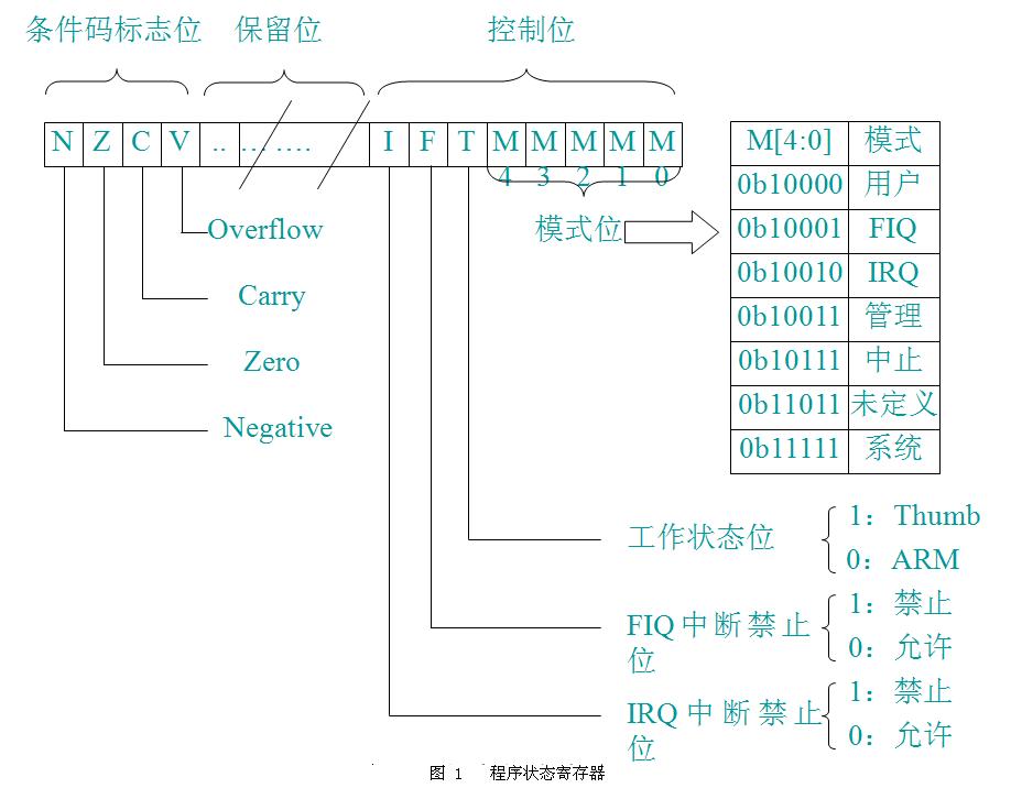
.balignl 16,0xdeadbeef设置CPU为SVC模式
msr	cpsr_c, #0xd3

@ I & F disable, Mode: 0x13 - SVC
0xd3 = 1101 0011 b,工作状态为arm态,关闭FIQ,IRQ,使工作模式为SVC。
L2 cache操作
bl	disable_l2cache				// 禁止L2 cache
bl	set_l2cache_auxctrl_cycle	// l2 cache相关初始化
bl	enable_l2cache				// 使能l2 cache
Invalidate L1 I/D
@ 刷新L1 cache的icache和dcache。
mov	r0, #0                  @ set up for MCR
mcr	p15, 0, r0, c8, c7, 0   @ invalidate TLBs
mcr	p15, 0, r0, c7, c5, 0   @ invalidate icache
关掉MMU
@ disable MMU stuff and caches

mrc	p15, 0, r0, c1, c0, 0
bic	r0, r0, #0x00002000     @ clear bits 13 (--V-)
bic	r0, r0, #0x00000007     @ clear bits 2:0 (-CAM)
orr	r0, r0, #0x00000002     @ set bit 1 (--A-) Align
orr	r0, r0, #0x00000800     @ set bit 12 (Z---) BTB
mcr 	p15, 0, r0, c1, c0, 0
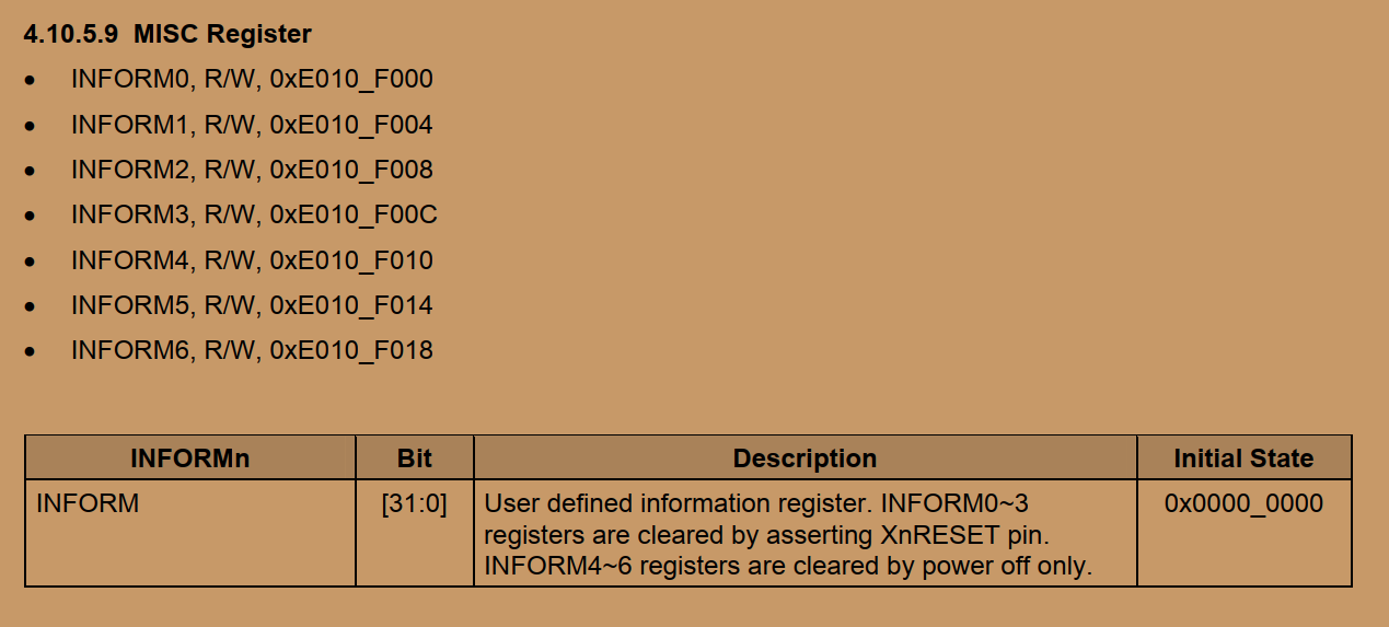
读取启动引脚信息
/* 在210内部有一个寄存器(地址是0xE0000004)
 * 这个寄存器中的值是硬件根据OM引脚的设置而自动设置值的
 * 可以通过读取这个寄存器的值然后判断其值来确定当前选中的启动介质是Nand还是SD还是其他的。
 */
ldr	r0, =PRO_ID_BASE
ldr	r1, [r0,#OMR_OFFSET]
bic	r2, r1, #0xffffffc1
经过一系列比较,得到
/* SD/MMC BOOT */
cmp     r2, #0xc	// c即为SD或MMC启动
moveq   r3, #BOOT_MMCSD
// r3中存储了0x03 然后再将0x3放入INFORM3寄存器

第一次设置栈
	ldr	sp, =0xd0036000 /* end of sram dedicated to u-boot */
	sub	sp, sp, #12	/* set stack */
	mov	fp, #0
这个栈地址设置在SROM中,并且没有按照三星要求来做。因为接下来需要调用C函数,所以需要先设置Stack。
./board/samsung/x210/lowlevel_init.S
主要完成关看门狗,供电锁存,判断当前代码执行位置,初始化时钟,初始化DDR,初始化串口。
第二次设置栈
	/* get ready to call C functions */
	ldr	sp, _TEXT_PHY_BASE	/* setup temp stack pointer */
	sub	sp, sp, #12
	mov	fp, #0			/* no previous frame, so fp=0 */
_TEXT_PHY_BASE = 0x33E0 0000,这里的栈设置在DDR中,沿着uboot起始地址向下。
再次判断当前代码执行的位置
判断是否进入SD2卡启动
#if defined(CONFIG_EVT1)
	/* If BL1 was copied from SD/MMC CH2 */
	ldr	r0, =0xD0037488		//	V210_SDMMC_BASE current boot channel
	ldr	r1, [r0]
	ldr	r2, =0xEB200000		//	SD卡通道二
	cmp	r1, r2
	beq     mmcsd_boot
#endif
当前启动状态与SD卡通道2的启动地址比较,进入mmcsd_boot。

#if DELETE
	ldr     sp, _TEXT_PHY_BASE
	sub     sp, sp, #12
	mov     fp, #0
#endif
	bl      movi_bl2_copy
	b       after_copy
进入movi_bl2_copy函数
./cpu/s5pc11x/movi.c
复制uboot代码到DDR中
void movi_bl2_copy(void)
{
	ulong ch;
#if defined(CONFIG_EVT1)
	ch = *(volatile u32 *)(0xD0037488);	// EB20_0000通道2启动
	copy_sd_mmc_to_mem copy_bl2 =
	    (copy_sd_mmc_to_mem) (*(u32 *) (0xD0037F98));

	#if defined(CONFIG_SECURE_BOOT)
	ulong rv;
	#endif
#else
	ch = *(volatile u32 *)(0xD003A508);
	copy_sd_mmc_to_mem copy_bl2 =
	    (copy_sd_mmc_to_mem) (*(u32 *) (0xD003E008));
#endif
	u32 ret;
	//	iNand
	if (ch == 0xEB000000) {
		ret = copy_bl2(0, MOVI_BL2_POS, MOVI_BL2_BLKCNT,
			CFG_PHY_UBOOT_BASE, 0);

#if defined(CONFIG_SECURE_BOOT)
		/* do security check */
		rv = Check_Signature( (SecureBoot_CTX *)SECURE_BOOT_CONTEXT_ADDR,
				      (unsigned char *)CFG_PHY_UBOOT_BASE, (1024*512-128),
			              (unsigned char *)(CFG_PHY_UBOOT_BASE+(1024*512-128)), 128 );
		if (rv != 0){
				while(1);
			}
#endif
	}
	// SD卡2
	else if (ch == 0xEB200000) {
		ret = copy_bl2(2, MOVI_BL2_POS, MOVI_BL2_BLKCNT,
			CFG_PHY_UBOOT_BASE, 0);

#if defined(CONFIG_SECURE_BOOT)
		/* do security check */
		rv = Check_Signature( (SecureBoot_CTX *)SECURE_BOOT_CONTEXT_ADDR,
				      (unsigned char *)CFG_PHY_UBOOT_BASE, (1024*512-128),
			              (unsigned char *)(CFG_PHY_UBOOT_BASE+(1024*512-128)), 128 );
		if (rv != 0) {
			while(1);
		}
#endif
	}
	else
		return;

	if (ret == 0)
		while (1)
			;
	else
		return;
} 从上一步图片中的寄存器判断是SD0还是SD2启动,然后再使用device copy function复制代码到DDR中。
使能MMU域访问(cp15的c3寄存器)
#if defined(CONFIG_ENABLE_MMU)
enable_mmu:
	/* enable domain access */
	ldr	r5, =0x0000ffff
	mcr	p15, 0, r5, c3, c0, 0		@load domain access register
设置TTB(cp15的c2寄存器)
	/* Set the TTB register */
	// 开启translation table base
	ldr	r0, _mmu_table_base
	ldr	r1, =CFG_PHY_UBOOT_BASE
	ldr	r2, =0xfff00000
	bic	r0, r0, r2
	orr	r1, r0, r1
	mcr	p15, 0, r1, c2, c0, 0
MMU映射表是其中关键。
	/* form a first-level section entry */
	// .macro用于生成宏,.endm用于结束宏,.word表示的数即为表项
.macro FL_SECTION_ENTRY base,ap,d,c,b
	.word (base << 20) | (ap << 10) |
	      (d << 5) | (1<<4) | (c << 3) | ( << 2) | (1<<1)
.endm
.section .mmudata, "a"
	.align 14
	// the following alignment creates the mmu table at address 0x4000.
	.globl mmu_table
mmu_table:
	.set __base,0
	// Access for iRAM
	// 伪指令.rept相当于循环开始,0x100为循环次数
	.rept 0x100
	FL_SECTION_ENTRY __base,3,0,0,0
	.set __base,__base+1
	// 循环结束
	.endr

	// Not Allowed
	.rept 0x200 - 0x100
	.word 0x00000000
	.endr

	.set __base,0x200
	// should be accessed
	.rept 0x600 - 0x200
	FL_SECTION_ENTRY __base,3,0,1,1
	.set __base,__base+1
	.endr

	.rept 0x800 - 0x600
	.word 0x00000000
	.endr

	.set __base,0x800
	// should be accessed
	.rept 0xb00 - 0x800
	FL_SECTION_ENTRY __base,3,0,0,0
	.set __base,__base+1
	.endr

/*	.rept 0xc00 - 0xb00
	.word 0x00000000
	.endr */

	.set __base,0xB00
	.rept 0xc00 - 0xb00
	FL_SECTION_ENTRY __base,3,0,0,0
	.set __base,__base+1
	.endr

	// 0xC000_0000映射到0x3000_0000
	.set __base,0x300
	//.set __base,0x200
	// 256MB for SDRAM with cacheable
	.rept 0xD00 - 0xC00
	FL_SECTION_ENTRY __base,3,0,1,1
	.set __base,__base+1
	.endr

	// access is not allowed.
	@.rept 0xD00 - 0xC80
	@.word 0x00000000
	@.endr

	.set __base,0xD00
	// 1:1 mapping for debugging with non-cacheable
	.rept 0x1000 - 0xD00
	FL_SECTION_ENTRY __base,3,0,0,0
	.set __base,__base+1
	.endr

#else // CONFIG_MCP_AC, CONFIG_MCP_H, CONFIG_MCP_B| 物理地址 | 映射地址 |
|---|---|
| 0x0000_0000-0FFF_FFFF | 0x0000_0000-0FFF_FFFF |
| 0x1000_0000-1FFF_FFFF | Not allowed |
| 0x2000_0000-5FFF_FFFF | 0x2000_0000-5FFF_FFFF |
| 0x6000_0000-7FFF_FFFF | Not allowed |
| 0x8000_0000-AFFF_FFFF | 0x8000_0000-AFFF_FFFF |
| 0xB000_0000-BFFF_FFFF | 0xB000_0000-BFFF_FFFF |
| 0xC000_0000-CFFF_FFFF | 0x3000_0000-3FFF_FFFF |
| 0xD000_0000-FFFF_FFFF | 0xD000_0000-FFFF_FFFF |
使能MMU
	/* Enable the MMU */
	// 使能MMU
mmu_on:
	mrc	p15, 0, r0, c1, c0, 0
	orr	r0, r0, #1
	mcr	p15, 0, r0, c1, c0, 0
	nop
	nop
第三次设置栈
	// 第三次设置栈
	/* Set up the stack						    */
stack_setup:
#if defined(CONFIG_MEMORY_UPPER_CODE)
ldr sp, =(CFG_UBOOT_BASE + CFG_UBOOT_SIZE - 0x1000) 其中CFG_UBOOT_BASE=0xC3E0_0000,CFG_UBOOT_SIZE=2M
清BBS段
clear_bss:
	ldr	r0, _bss_start		/* find start of bss segment        */
	ldr	r1, _bss_end		/* stop here                        */
	mov 	r2, #0x00000000		/* clear                            */

clbss_l:
	str	r2, [r0]		/* clear loop...                    */
	add	r0, r0, #4
	cmp	r0, r1
	ble	clbss_l
进入BL2
	ldr	pc, _start_armboot

_start_armboot:
	.word start_armboot
2.lowlevel_init.S分析
lr压栈
push {lr}检查复位状态
CPU允许多种复位状况。我们需要在复位代码中检测复位状态。
	ldr	r0, =(ELFIN_CLOCK_POWER_BASE+RST_STAT_OFFSET)
	ldr	r1, [r0]
	bic	r1, r1, #0xfff6ffff
	cmp	r1, #0x10000
	beq	wakeup_reset_pre
	cmp	r1, #0x80000
	beq	wakeup_reset_from_didle
IO状态恢复
	ldr	r0, =(ELFIN_CLOCK_POWER_BASE + OTHERS_OFFSET)
	ldr	r1, [r0]
	ldr	r2, =IO_RET_REL
	orr	r1, r1, r2
	str	r1, [r0]
关看门狗
	ldr	r0, =ELFIN_WATCHDOG_BASE	/* 0xE2700000 */
	mov	r1, #0
	str	r1, [r0]
SRAM与SROM配置
略过。
供电锁存
	/* PS_HOLD pin(GPH0_0) set to high */
	ldr	r0, =(ELFIN_CLOCK_POWER_BASE + PS_HOLD_CONTROL_OFFSET)
	ldr	r1, [r0]
	orr	r1, r1, #0x300
	orr	r1, r1, #0x1
	str	r1, [r0]
判断当前代码执行的位置
	/* when we already run in ram, we don't need to relocate U-Boot.
	 * and actually, memory controller must be configured before U-Boot
	 * is running in ram.
	 */
	ldr	r0, =0xff000fff
	bic	r1, pc, r0		/* r0 <- current base addr of code */
	ldr	r2, _TEXT_BASE		/* r1 <- original base addr in ram */
	bic	r2, r2, r0		/* r0 <- current base addr of code */
	cmp     r1, r2                  /* compare r0, r1                  */
	beq     1f			/* r0 == r1 then skip sdram init   */
	//	1表示编号,f表示
	forward,向后找
这里采用的方法是截取现在地址的12-14位,以及链接时地址的12-14位,如果相等,则可以判断程序已经在DDR中,否则可认为程序仍然在SROM中。
初始化系统时钟
进入system_clock_init函数
初始化DDR
进入mem_ctrl_asm_init函数,DMC0_MEMCONFIG_0,在裸机中配置值为0x20E01323;在uboot中配置为0x30F01313.这个配置不同就导致结果不同。
在 裸机中DMC0的256MB内存地址范围是0x20000000-0x2FFFFFFF;
在uboot中DMC0的256MB内存地址范围为0x30000000-0x3FFFFFFF。
初始化串口,发送O
进入uart_asm_init函数,初始化完成后发送一个O。
trust zone初始化
进入tzpc_init函数
串口发送K
发送K后,返回pop {pc}。
三、我认为有用的步骤
