常用命令总结:
bridge-domain bd-id,创建广播域BD,并进入BD视图。
description description,配置BD的描述信息。
l2 binding vlan vlan-id,将指定VLAN与BD相关联,实现数据报文在BD内进行转发。
vxlan vni vni-id,配置BD所对应的VXLAN的VNI.
source ip-address,配置VXLAN隧道源端VTEP的IP地址。
vni vni-id head-end peer-list ip-address &<1-10>,配置头端复制列表。
display bridge-domain [ bd-id [ brief | verbose ] ],查看BD的配置信息。
display vxlan tunnel [ tunnel-id ] [ verbose ],查看VXLAN隧道的信息。
display vxlan vni [ vni-id [ verbose ] ],查看VNI的VXLAN的配置信息。
display vxlan peer [ vni vni-id ],查看VNI的目的端VTEP的IP地址。
display bridge-domain bd-id statistics,查看BD内报文的统计信息。
display vxlan statistics source source-ip-address peer peer-ip-address [ vni vni-id ],查看VXLAN隧道报文的统计信息。
reset bridge-domain bd-id statistics,清除指定BD内流量统计信息。
reset vxlan statistics source source-ip-address peer peer-ip-address [ vni vni-id ],清除VXLAN隧道报文统计信息。
通过VXLAN 在园区上构建虚拟数据中心网络(二层互通)示例
1.组网需求
企业已经建成比较成熟的园区网络,但是没有专用的数据中心网络,所有的服务器分布在不同的部门,并且不具备集中放置的条件。现在用户希望在已有园区网络上构建一个虚拟的数据中心网络,需求如下:
1)将散落在不同部门的服务器构建成一个虚拟网络,实现资源整合和业务灵活部署。
2)各服务器上部署着大量的VM,相同业务的VM之间需要实现二层互通。
3)各VM之间由于业务需求需要在服务器之间进行平滑迁移,且保证业务不中断。
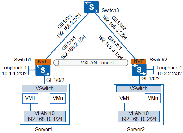
如下图所示,企业在不同的数据中心都拥有自己的VM,Server1与Server2上的VM1都属于VLAN 10,现需要通过VXLAN隧道实现相同业务的VM之间的二层互通。
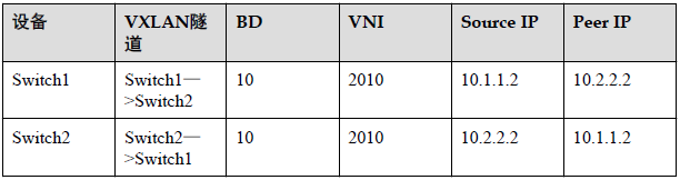
2.数据准备
3.配置思路
采用如下思路配置同网段用户通过VXLAN隧道互通:
1. 分别在Switch1、Switch2、Switch3上配置路由协议,保证网络三层互通。
2. 分别在Switch1、Switch2上配置VXLAN接入业务部署方式。
3. 分别在Switch1、Switch2上配置VXLAN隧道。
4.操作步骤
1)配置路由协议
# 配置Switch1各接口IP地址。Switch2和Switch3的配置与Switch1类似,这里不再赘述。配置OSPF时,注意需要发布设备上的32位Loopback接口地址。
<Quidway> system-view
[Quidway] sysname Switch1
[Switch1] interface loopback 1
[Switch1-LoopBack1] ip address 10.1.1.2 32
[Switch1-LoopBack1] quit
[Switch1] interface gigabitethernet 1/0/1
[Switch1-GigabitEthernet1/0/1] undo portswitch
[Switch1-GigabitEthernet1/0/1] ip address 192.168.2.1 24
[Switch1-GigabitEthernet1/0/1] quit
[Switch1] ospf router-id 10.1.1.2
[Switch1-ospf-1] area 0
[Switch1-ospf-1-area-0.0.0.0] network 10.1.1.2 0.0.0.0
[Switch1-ospf-1-area-0.0.0.0] network 192.168.2.0 0.0.0.255
# OSPF成功配置后,Switch之间可通过OSPF协议发现对方的Loopback接口的IP地址,并能互相ping通。
2)分别在Switch1、Switch2上配置业务接入点
# 配置Switch1。
[Switch1] bridge-domain 10
[Switch1-bd10] quit
[Switch1] interface gigabitethernet 1/0/2
[Switch1-GigabitEthernet1/0/2] port link-type trunk
[Switch1-GigabitEthernet1/0/2] quit
[Switch1] interface gigabitethernet 1/0/2.1 mode l2
[Switch1-GigabitEthernet1/0/2.1] encapsulation dot1q vid 10
[Switch1-GigabitEthernet1/0/2.1] bridge-domain 10
# 配置Switch2。
[Switch2] bridge-domain 10
[Switch2-bd10] quit
[Switch2] interface gigabitethernet 1/0/2
[Switch2-GigabitEthernet1/0/2] port link-type trunk
[Switch2-GigabitEthernet1/0/2] quit
[Switch2] interface gigabitethernet 1/0/2.1 mode l2
[Switch2-GigabitEthernet1/0/2.1] encapsulation dot1q vid 10
[Switch2-GigabitEthernet1/0/2.1] bridge-domain 10
3)分别在Switch1、Switch2上配置VXLAN隧道
# 配置Switch1。
[Switch1] bridge-domain 10
[Switch1-bd10] vxlan vni 2010
[Switch1-bd10] quit
[Switch1] interface nve 1
[Switch1-Nve1] source 10.1.1.2
[Switch1-Nve1] vni 2010 head-end peer-list 10.2.2.2
# 配置Switch2。
[Switch2] bridge-domain 10
[Switch2-bd10] vxlan vni 2010
[Switch2-bd10] quit
[Switch2] interface nve 1
[Switch2-Nve1] source 10.2.2.2
[Switch2-Nve1] vni 2010 head-end peer-list 10.1.1.2
4)验证配置结果
# 上述配置成功后,在Switch1、Switch2上执行display vxlan vni命令可查看到VNI的状态是Up;执行display vxlan tunnel命令可查看到VXLAN隧道的信息。以Switch1显示为例。
[Switch1] display vxlan vni
VNI BD-ID State
-----------------------------------------
2010 10 up
-----------------------------------------
Number of vxlan vni bound to BD is : 1
[Switch1] display vxlan tunnel
Tunnel ID Source Destination State Type
----------------------------------------------------------------------------
4026531841 10.1.1.2 10.2.2.2 up static
----------------------------------------------------------------------------
Number of vxlan tunnel : 1
# 配置完成后,同网段用户通过VXLAN隧道可以互通。
5.配置文件
Switch1的配置文件
sysname Switch1
#
bridge-domain 10
vxlan vni 2010
#
interface GigabitEthernet1/0/1
undo portswitch
ip address 192.168.2.1 255.255.255.0
#
interface GigabitEthernet1/0/2
port link-type trunk
#
interface GigabitEthernet1/0/2.1 mode l2
encapsulation dot1q vid 10
bridge-domain 10
#
interface LoopBack1
ip address 10.1.1.2 255.255.255.255
#
interface Nve1
source 10.1.1.2
vni 2010 head-end peer-list 10.2.2.2
#
ospf 1 router-id 10.1.1.2
area 0.0.0.0
network 10.1.1.2 0.0.0.0
network 192.168.2.0 0.0.0.255
#
return
Switch2的配置文件
sysname Switch2
#
bridge-domain 10
vxlan vni 2010
#
interface GigabitEthernet1/0/1
undo portswitch
ip address 192.168.3.1 255.255.255.0
#
interface GigabitEthernet1/0/2
port link-type trunk
#
interface GigabitEthernet1/0/2.1 mode l2
encapsulation dot1q vid 10
bridge-domain 10
#
interface LoopBack1
ip address 10.2.2.2 255.255.255.255
#
interface Nve1
source 10.2.2.2
vni 2010 head-end peer-list 10.1.1.2
#
ospf 1 router-id 10.2.2.2
area 0.0.0.0
network 10.2.2.2 0.0.0.0
network 192.168.3.0 0.0.0.255
#
return
Switch3的配置文件
sysname Switch3
#
interface GigabitEthernet1/0/1
undo portswitch
ip address 192.168.2.2 255.255.255.0
#
interface GigabitEthernet1/0/2
undo portswitch
ip address 192.168.3.2 255.255.255.0
#
ospf 1 router-id 192.168.2.2
area 0.0.0.0
network 192.168.2.0 0.0.0.255
network 192.168.3.0 0.0.0.255
#
return
通过VXLAN 在园区上构建虚拟数据中心网络(三层互通)示例
1.组网需求
企业已经建成比较成熟的园区网络,但是没有专用的数据中心网络,所有的服务器分布在不同的部门,并且不具备集中放置的条件。现在用户希望在已有园区网络上构建一个虚拟的数据中心网络,需求如下:
将散落在不同部门的服务器构建成一个虚拟网络,实现资源整合和业务灵活部署。
各服务器上部署着大量的VM,不同业务的VM之间需要实现三层互通。
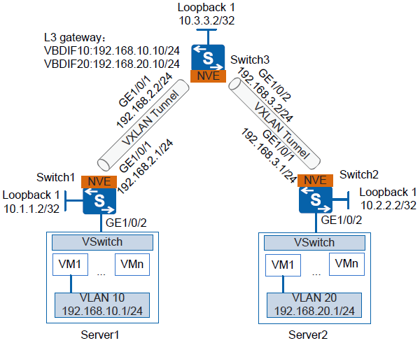
如下图所示,企业在不同的数据中心都拥有自己的VM,Server1上的VM1属于VLAN10,Server2上的VM1属于VLAN 20,现需要通过VXLAN隧道实现不同业务的VM之间的三层互通。
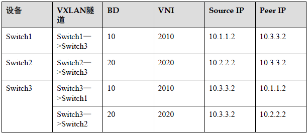
2.数据准备
3.配置思路
采用如下思路配置不同网段用户通过VXLAN网关互通:
1. 分别在Switch1、Switch2、Switch3上配置路由协议,保证网络三层互通。
2. 分别在Switch1、Switch2上配置VXLAN接入业务部署方式。
3. 分别在Switch1、Switch2、Switch3上配置VXLAN隧道。
4. 在Switch3上配置VXLAN三层网关。
4.操作步骤
1)配置路由协议
# 配置Switch1各接口IP地址。Switch2和Switch3的配置与Switch1类似,这里不再赘述。配置OSPF时,注意需要发布设备上的32位Loopback接口地址。
<Quidway> system-view
[Quidway] sysname Switch1
[Switch1] interface loopback 1
[Switch1-LoopBack1] ip address 10.1.1.2 32
[Switch1-LoopBack1] quit
[Switch1] interface gigabitethernet 1/0/1
[Switch1-GigabitEthernet1/0/1] undo portswitch
[Switch1-GigabitEthernet1/0/1] ip address 192.168.2.1 24
[Switch1-GigabitEthernet1/0/1] quit
[Switch1] ospf router-id 10.1.1.2
[Switch1-ospf-1] area 0
[Switch1-ospf-1-area-0.0.0.0] network 10.1.1.2 0.0.0.0
[Switch1-ospf-1-area-0.0.0.0] network 192.168.2.0 0.0.0.255
# OSPF成功配置后,Switch之间可通过OSPF协议发现对方的Loopback接口的IP地址,并能互相ping通。
2)分别在Switch1、Switch2上配置业务接入点
# 配置Switch1。
[Switch1] bridge-domain 10
[Switch1-bd10] quit
[Switch1] interface gigabitethernet 1/0/2
[Switch1-GigabitEthernet1/0/2] port link-type trunk
[Switch1-GigabitEthernet1/0/2] quit
[Switch1] interface gigabitethernet 1/0/2.1 mode l2
[Switch1-GigabitEthernet1/0/2.1] encapsulation dot1q vid 10
[Switch1-GigabitEthernet1/0/2.1] bridge-domain 10
# 配置Switch2。
[Switch2] bridge-domain 20
[Switch2-bd20] quit
[Switch2] interface gigabitethernet 1/0/2
[Switch2-GigabitEthernet1/0/2] port link-type trunk
[Switch2-GigabitEthernet1/0/2] quit
[Switch2] interface gigabitethernet 1/0/2.1 mode l2
[Switch2-GigabitEthernet1/0/2.1] encapsulation dot1q vid 20
[Switch2-GigabitEthernet1/0/2.1] bridge-domain 20
3)分别在Switch1、Switch2、Switch3上配置VXLAN隧道
# 配置Switch1。
[Switch1] bridge-domain 10
[Switch1-bd10] vxlan vni 2010
[Switch1-bd10] quit
[Switch1] interface nve 1
[Switch1-Nve1] source 10.1.1.2
[Switch1-Nve1] vni 2010 head-end peer-list 10.3.3.2
# 配置Switch2。
[Switch2] bridge-domain 20
[Switch2-bd20] vxlan vni 2020
[Switch2-bd20] quit
[Switch2] interface nve 1
[Switch2-Nve1] source 10.2.2.2
[Switch2-Nve1] vni 2020 head-end peer-list 10.3.3.2
# 配置Switch3.
[Switch3] bridge-domain 10
[Switch3-bd10] vxlan vni 2010
[Switch3-bd10] quit
[Switch3] interface nve 1
[Switch3-Nve1] source 10.3.3.2
[Switch3-Nve1] vni 2010 head-end peer-list 10.1.1.2
[Switch3-Nve1] quit
[Switch3] bridge-domain 20
[Switch3-bd20] vxlan vni 2020
[Switch3-bd20] quit
[Switch3] interface nve 1
[Switch3-Nve1] source 10.3.3.2
[Switch3-Nve1] vni 2020 head-end peer-list 10.2.2.2
4)在Switch3上配置VXLAN三层网关
[Switch3] interface vbdif 10
[Switch3-Vbdif10] ip address 192.168.10.10 24
[Switch3-Vbdif10] quit
[Switch3] interface vbdif 20
[Switch3-Vbdif20] ip address 192.168.20.10 24
5)验证配置结果
# 上述配置成功后,在Switch1、Switch2上执行命令display vxlan vni可查看到VNI的状态是Up;执行命令display vxlan tunnel可查看到VXLAN隧道的信息。以Switch3显示为例。
[Switch3] display vxlan vni
VNI BD-ID State
-----------------------------------------
2010 10 up
2020 20 up
-----------------------------------------
Number of vxlan vni bound to BD is : 2
[Switch3] display vxlan tunnel
Tunnel ID Source Destination State Type
----------------------------------------------------------------------------
4026531842 10.3.3.2 10.1.1.2 up static
4026531841 10.3.3.2 10.2.2.2 up static
----------------------------------------------------------------------------
Number of vxlan tunnel : 2
# 配置完成后,不同网段用户通过VXLAN网关可以互通。
5.配置文件
Switch1的配置文件
sysname Switch1
#
bridge-domain 10
vxlan vni 2010
#
interface GigabitEthernet1/0/1
undo portswitch
ip address 192.168.2.1 255.255.255.0
#
interface GigabitEthernet1/0/2
port link-type trunk
#
interface GigabitEthernet1/0/2.1 mode l2
encapsulation dot1q vid 10
bridge-domain 10
#
interface LoopBack1
ip address 10.1.1.2 255.255.255.255
#
interface Nve1
source 10.1.1.2
vni 2010 head-end peer-list 10.3.3.2
#
ospf 1 router-id 10.1.1.2
area 0.0.0.0
network 10.1.1.2 0.0.0.0
network 192.168.2.0 0.0.0.255
#
return
Switch2的配置文件
sysname Switch2
#
bridge-domain 20
vxlan vni 2020
#
interface GigabitEthernet1/0/1
undo portswitch
ip address 192.168.3.1 255.255.255.0
#
interface GigabitEthernet1/0/2
port link-type trunk
#
interface GigabitEthernet1/0/2.1 mode l2
encapsulation dot1q vid 20
bridge-domain 20
#
interface LoopBack1
ip address 10.2.2.2 255.255.255.255
#
interface Nve1
source 10.2.2.2
vni 2020 head-end peer-list 10.3.3.2
#
ospf 1 router-id 10.2.2.2
area 0.0.0.0
network 10.2.2.2 0.0.0.0
network 192.168.3.0 0.0.0.255
#
return
Switch3的配置文件
sysname Switch3
#
bridge-domain 10
vxlan vni 2010
bridge-domain 20
vxlan vni 2020
#
interface Vbdif10
ip address 192.168.10.10 255.255.255.0
#
interface Vbdif20
ip address 192.168.20.10 255.255.255.0
#
interface GigabitEthernet1/0/1
undo portswitch
ip address 192.168.2.2 255.255.255.0
#
interface GigabitEthernet1/0/2
undo portswitch
ip address 192.168.3.2 255.255.255.0
#
interface LoopBack1
ip address 10.3.3.2 255.255.255.255
#
interface Nve1
source 10.3.3.2
vni 2010 head-end peer-list 10.1.1.2
vni 2020 head-end peer-list 10.2.2.2
#
ospf 1 router-id 10.3.3.2
area 0.0.0.0
network 10.3.3.2 0.0.0.0
network 192.168.2.0 0.0.0.255
network 192.168.3.0 0.0.0.255
#
return