2013年3月31日 17:00:11
工程文件位置:
E:\Documents\program\Routine\example\LPC1220_UART\LPC1220_UART_AUTOBAUD\LPC1220_UART_AUTOBAUD.xmp
main.c文件的内容:
1 /****************************************Copyright (c)****************************************************
2 ** Guangzhou ZLGMCU Development Co., LTD
3 **
4 ** http://www.zlgmcu.com
5 **
6 **--------------File Info---------------------------------------------------------------------------------
7 ** File name: main.c
8 ** Last modified Date: 2010-11-04
9 ** Last Version: V1.0
10 ** Descriptions: The main() function example template
11 **
12 **--------------------------------------------------------------------------------------------------------
13 ** Created by: He Zengfu
14 ** Created date: 2010-11-20
15 ** Version: V1.00
16 ** Descriptions: 整理模板,添加用户应用程序
17 **
18 **--------------------------------------------------------------------------------------------------------
19 ** Modified by: Wu Yuanlang
20 ** Modified date: 2010-12-20
21 ** Version: V1.00
22 ** Descriptions: 编写UART自动波特率例程
23 **
24 **--------------------------------------------------------------------------------------------------------
25 ** Modified by: Wu yuanlang
26 ** Modified date: 2010-12-24
27 ** Version: V1.00
28 ** Descriptions: 检查、测试程序,并添加、修改注释和程序风格
29 **
30 ** Rechecked by:
31 *********************************************************************************************************/
32 #include "lpc12xx_libcfg.h"
33 #include "stdio.h"
34 #include "led.h"
35
36 /*********************************************************************************************************
37 宏定义
38 *********************************************************************************************************/
39 #define UART_LCR_DLAB_EN ((uint8_t)(1<<7)) /* 除数锁存位 ox80 */
40 #define UART_ACR_START ((uint32_t)(1<<0)) /* 自动波特率启动位 0x01 */
41
42 #define UART_PORT 1 /* 定义使用的UART端口 使用串口1 */
43
44 //根据串口,选择合适的串口定义.
45 #if (UART_PORT == 0)
46 #define TEST_UART LPC_UART0
47 #define TEST_UART_RXD IOCON_UART_RXD0_LOC0
48 #define TEST_UART_TXD IOCON_UART_TXD0_LOC0
49
50 #elif (UART_PORT == 1)
51 #define TEST_UART LPC_UART1
52 #define TEST_UART_RXD IOCON_UART_RXD1_LOC0
53 #define TEST_UART_TXD IOCON_UART_TXD1_LOC0
54 #endif
55
56 /*********************************************************************************************************
57 全局变量定义
58 *********************************************************************************************************/
59 uint8_t GucDlm; /* 用于保存波特率的除数寄存器值 */
60 uint8_t GucDll;
61 uint32_t GulBaud;
62 char GcStr[64];
63
64 /*********************************************************************************************************
65 ** Function name: uartInit
66 ** Descriptions: 串口初始化,设置为8位数据位,1位停止位,无奇偶校验
67 ** input parameters: 无
68 ** output parameters: 无
69 ** Returned value: 无
70 *********************************************************************************************************/
71 void uartInit (void)
72 {
73 UART_CFG_Type UARTConfigStruct;
74 IOCON_PIO_CFG_Type PIO_mode;
75
76 IOCON_StructInit(&PIO_mode);
77
78
79 /* 设置引脚为TXD、RXD功能 */
80 PIO_mode.type = TEST_UART_RXD;
81 IOCON_SetFunc(&PIO_mode);
82 PIO_mode.type = TEST_UART_TXD;
83 IOCON_SetFunc(&PIO_mode);
84
85
86
87 #if (UART_PORT == 0) /* 打开UART时钟模块 */
88 SYS_ResetPeripheral(SYS_PRESETCTRL_UART0_RST,DISABLE); //复位外设
89 SYS_ConfigAHBCLK(SYS_AHBCLKCTRL_UART0, ENABLE); //外设时钟配置
90 SYS_SetUART0ClockDiv(1); //设置分频系数
91 #endif
92
93 #if (UART_PORT == 1)
94 SYS_ResetPeripheral(SYS_PRESETCTRL_UART1_RST,DISABLE);
95 SYS_ConfigAHBCLK(SYS_AHBCLKCTRL_UART1, ENABLE);
96 SYS_SetUART1ClockDiv(1);
97 #endif
98
99 UART_Init(TEST_UART); //初始化串口//复位串口 /* 使能UART */
100
101 /* 将参数赋值给UARTConfigStruct */
102 UART_GetConfig(TEST_UART, &UARTConfigStruct); //将生成的空结构体作为现在要用的串口的配置结构体.
103
104 /* 设置为8位数据 */
105 UARTConfigStruct.databits = UART_CFG_DATABIT_8; //现在配置结构体:设置为8位数据.
106
107 /* 更新配置参数 */
108 UART_SetConfig(TEST_UART, &UARTConfigStruct); //对结构体成员赋值.
109
110 /* 使能发送功能 */
111 UART_ConfigTXD(TEST_UART, ENABLE); //
112 }
113
114 /*********************************************************************************************************
115 ** Function name: uartSendByte
116 ** Descriptions: 向串口发送字节数据,并等待数据发送完成,使用查询方式
117 ** input parameters: ucDat: 要发送的数据
118 ** output parameters: 无
119 ** Returned value: 无
120 *********************************************************************************************************/
121 void uartSendByte (uint8_t ucDat)
122 {
123 UART_Send(TEST_UART, &ucDat, 1, UART_BLOKING_TIMEOUT); /* 写入数据 */
124 while (!(UART_GetLineStatus(TEST_UART) & UART_LS_TX_EMPTY_ALL)); /* 等待数据发送完毕 */
125 }
126
127 /*********************************************************************************************************
128 ** Function name: uartSendStr
129 ** Descriptions: 向串口发送字符串
130 ** input parameters: pucStr: 要发送的字符串指针
131 ** output parameters: 无
132 ** Returned value: 无
133 *********************************************************************************************************/
134 void uartSendStr (char *pcStr)
135 {
136 while (1){
137 if (*pcStr == '\0') break; /* 遇到结束符,退出 */
138 uartSendByte(*pcStr++);
139 }
140 }
141
142 /*********************************************************************************************************
143 ** Function name: main
144 ** Descriptions: 主函数(函数入口)
145 ** 串口参数: UART波特率9600、8个数据位、1个停止位、无奇偶校验位
146 ** 跳线连接: P0.8(RXD1)、P0.9(TXD1)(若使用UART0则连接P0.1(RXD0)和P0.2(TXD0))通过232电平
147 ** 转换芯片分别连接到PC机串口的TXD、RXD;
148 ** 操作方法: 打开串口调试软件,运行程序,下位机等待PC向串口发送字符'a'或'A',观察显示窗口
149 ** 现 象: 串口调试软件显示当前波特率
150 ** input parameters: 无
151 ** output parameters: 无
152 ** Returned value: 无
153 *********************************************************************************************************/
154 int main (void)
155 {
156 SystemInit(); /* 系统时钟初始化 */
157 SYS_ConfigAHBCLK(SYS_AHBCLKCTRL_IOCON, ENABLE); /* IOCON模块时钟使能 */
158 SYS_ConfigAHBCLK(SYS_AHBCLKCTRL_GPIO1, ENABLE); /* GPIO1时钟使能 */
159
160 ledInit(); /* LED初始化 */
161
162
163 uartInit(); /* 串口初始化 */
164
165 while (1) {
166
167
168 /* 启动自动波特率 */
169 UART_StartAutoBaud(TEST_UART, UART_CFG_AUTOBAUD_MODE0, UART_CFG_ABRESTART_ENABLE);
170
171 /* 等待计算波特率完成 */
172 while (TEST_UART->ACR & UART_ACR_START) // (ACR=1) 与 (UART_ACR_START=1) //在自动波特率功能结束后,系统会清除UART_ACR_START此位。
173 {
174 //等待的过程中等闪烁.
175 ledOn();
176 myDelay(100);
177 ledOff();
178 myDelay(200);
179
180 }
181
182 /* 读取除数锁存器 */
183 //在LCR的DLAB=1的前提下读取DLL,DLM,然后清除LCR的DLAB
184 TEST_UART->LCR |= UART_LCR_DLAB_EN;
185 GucDll = TEST_UART->DLL;
186 GucDlm = TEST_UART->DLM;
187 TEST_UART->LCR &= ~UART_LCR_DLAB_EN;
188
189 /* 波特率计算,存在一定的误差 */
190 //波特率计算公式: UARTbaudrate=PCLK/(16*(256*DLM+DLL)*(1+DivAddVal/MulVal))
191 GulBaud = (MainClock / (16 * (256 * GucDlm + GucDll)));
192
193 /* 处理要发送的数据,然后向串口发送字符串 */
194 //函数原型int sprintf( char *buffer, const char *format [, argument] ... );
195 // (1)格式化字符串上。
196 // (2)字符/Ascii 码对照
197 // (3)连接字符串
198 //三个参数,保存数据的目的指针,格式,数据源指针. 将数据源格式化保存到数据目的指针处.
199 sprintf(GcStr, " Baud is %4d bps \n", GulBaud);
200 uartSendStr(GcStr);
201
202 }
203 }
204
205 #ifdef DEBUG
206 /*********************************************************************************************************
207 ** Function name: check_failed
208 ** Descriptions:
209 ** input parameters: 无
210 ** output parameters: 无
211 ** Returned value: 无
212 *********************************************************************************************************/
213 void check_failed (uint8_t *file, uint32_t line)
214 {
215 while(1); /* Infinite loop */
216 }
217
218 #endif
219
220 /*********************************************************************************************************
221 End Of File
222 *********************************************************************************************************/
下面详细分析这个函数和调用到的函数.
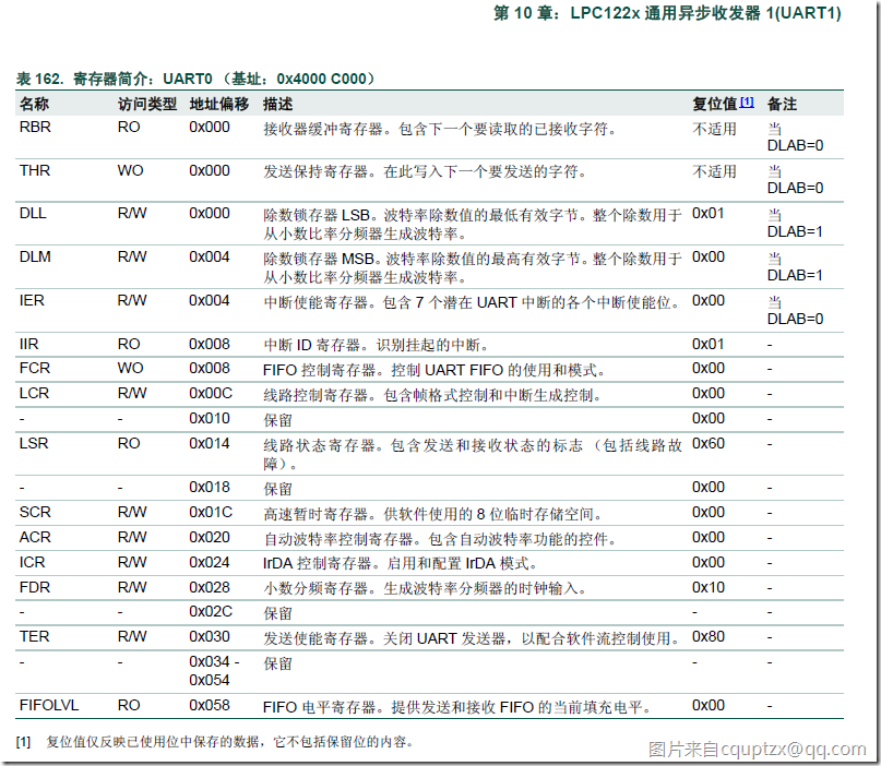
对于串口的寄存器,先列表出来他们:
我们用的主要是
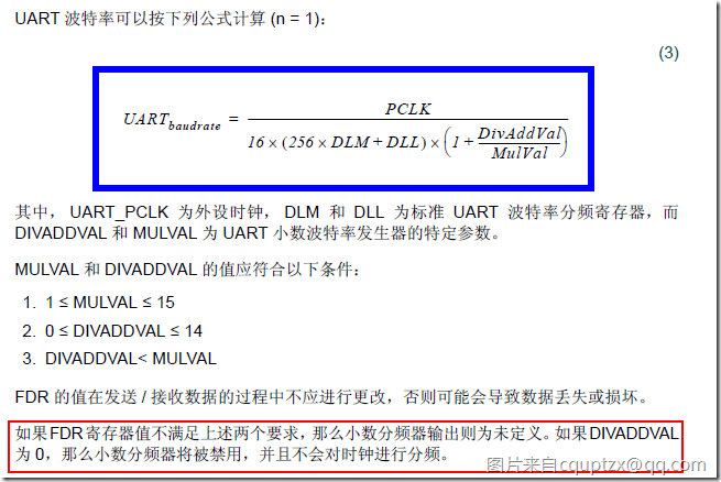
波特率的计算公式如下:
1.宏定义:
#define UART_LCR_DLAB_EN ((uint8_t)(1<<7)) /* 除数锁存位 ox80 */
#define UART_ACR_START ((uint32_t)(1<<0)) /* 自动波特率启动位 0x01 */
这两个宏定义分别对应的是
2.串口引脚寄存器宏定义(起别名):
44 //根据串口,选择合适的串口定义.
45 #if (UART_PORT == 0)
46 #define TEST_UART LPC_UART0
47 #define TEST_UART_RXD IOCON_UART_RXD0_LOC0
48 #define TEST_UART_TXD IOCON_UART_TXD0_LOC0
49
50 #elif (UART_PORT == 1)
51 #define TEST_UART LPC_UART1
52 #define TEST_UART_RXD IOCON_UART_RXD1_LOC0
53 #define TEST_UART_TXD IOCON_UART_TXD1_LOC0
54 #endif
由于有两个串口,所以通过串口的选择来定义相关的引脚寄存器
3.用于计算和保存波特率的全局变量
59 uint8_t GucDlm; /* 用于保存波特率的除数寄存器值 */
60 uint8_t GucDll;
61 uint32_t GulBaud;
62 char GcStr[64];
GucDlm,GucDll,GulBauld,GcStr分别对应DLM,DLL,BauldRate,最后发送的字符串.
4.串口初始化过程
64 /*********************************************************************************************************
65 ** Function name: uartInit
66 ** Descriptions: 串口初始化,设置为8位数据位,1位停止位,无奇偶校验
67 ** input parameters: 无
68 ** output parameters: 无
69 ** Returned value: 无
70 *********************************************************************************************************/
71 void uartInit (void)
72 {
73 UART_CFG_Type UARTConfigStruct;
74 IOCON_PIO_CFG_Type PIO_mode;
75
76 IOCON_StructInit(&PIO_mode);
77
78
79 /* 设置引脚为TXD、RXD功能 */
80 PIO_mode.type = TEST_UART_RXD;
81 IOCON_SetFunc(&PIO_mode);
82 PIO_mode.type = TEST_UART_TXD;
83 IOCON_SetFunc(&PIO_mode);
84
85
86
87 #if (UART_PORT == 0) /* 打开UART时钟模块 */
88 SYS_ResetPeripheral(SYS_PRESETCTRL_UART0_RST,DISABLE); //复位外设
89 SYS_ConfigAHBCLK(SYS_AHBCLKCTRL_UART0, ENABLE); //外设时钟配置
90 SYS_SetUART0ClockDiv(1); //设置分频系数
91 #endif
92
93 #if (UART_PORT == 1)
94 SYS_ResetPeripheral(SYS_PRESETCTRL_UART1_RST,DISABLE);
95 SYS_ConfigAHBCLK(SYS_AHBCLKCTRL_UART1, ENABLE);
96 SYS_SetUART1ClockDiv(1);
97 #endif
98
99 UART_Init(TEST_UART); //初始化串口//复位串口 /* 使能UART */
100
101 /* 将参数赋值给UARTConfigStruct */
102 UART_GetConfig(TEST_UART, &UARTConfigStruct); //将生成的空结构体作为现在要用的串口的配置结构体.
103
104 /* 设置为8位数据 */
105 UARTConfigStruct.databits = UART_CFG_DATABIT_8; //现在配置结构体:设置为8位数据.
106
107 /* 更新配置参数 */
108 UART_SetConfig(TEST_UART, &UARTConfigStruct); //对结构体成员赋值.
109
110 /* 使能发送功能 */
111 UART_ConfigTXD(TEST_UART, ENABLE); //
112 }
4.1串口初始化的大致过程:
4.2空串口配置结构体
UART_CFG_Type UARTConfigStruct;
typedef struct {
uint32_t baudrate; /* !< UART baud rate */ 波特率
uint8_t databits; /* !< Number of data bits
This parameter can be a value of @ref UART_databit_type */ //数据位
uint8_t stopbits; /* !< Number of stop bits
This parameter can be a value of @ref UART_stopbit_type */ //停止位
uint8_t parity; /* !< Parity selection
This parameter can be a value of @ref UART_parity_type */ //优先级
uint8_t fifolevel; /* !< Rx FIFO trigger level
This parameter can be a value of @ref FIFO_level_type */ //FIFO等级
uint8_t fifodma; /* !< DMA mode
This parameter can be a value of @ref FIFO_dmamode_type */ //FIFO直接内存读取
uint8_t txdbreak; /* !< enable: TXD forceed to logic 0
This parameter can be a value of @ref TXD_break_forced_type */ //txdbreak 中断?
} UART_CFG_Type;
4.3空IO引脚配置结构体
IOCON_PIO_CFG_Type PIO_mode;
typedef struct {
uint16_t type; /*!< low 8 bits is address offset, other is func >//低八位是地址偏移,其余的是功能函数
This parameter can be a value of @ref PIO_type */
uint8_t pinmode; /*!< Pin mode >引脚模式
This parameter can be a value of @ref PIO_pin_mode */
uint8_t invert; /*!< Inverted function >电平反转
This parameter can be a value of @ref Invert_input_mode */
uint8_t ad; /*!< analog/digital mode >AD模数
This parameter can be a value of @ref Analog_digital_mode */
uint16_t pmode; /*!< Push/pull mode for I2C >I2C类型,上拉还是推挽.
This parameter can be a value of @ref Push_Pull_mode */
uint16_t od; /*!< Open drive >开漏模式
This parameter can be a value of @ref Open_drain_mode */
uint16_t drive; /*!< Pin driver function >驱动电流模式
This parameter can be a value of @ref Drive_current_mode */
uint16_t sm; /*!< Sample mode >采样模式
This parameter can be a value of @ref Sample_mode */
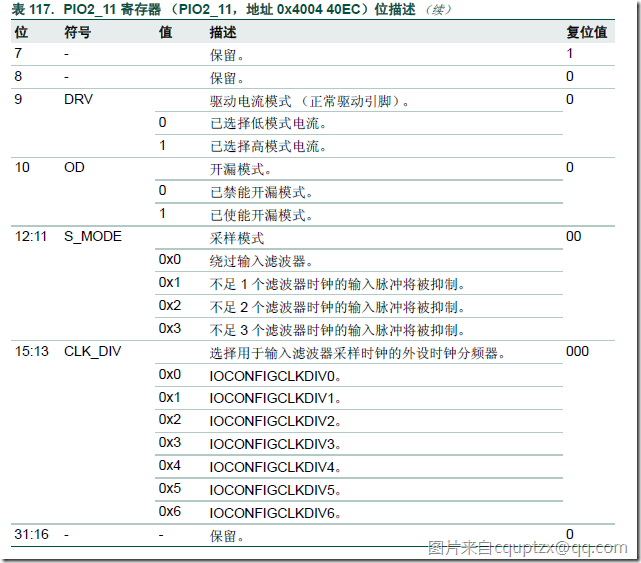
uint32_t cd; /*!< Clock Divider >选择用于输入滤波器采样时钟的外设时钟分频器
This parameter can be a value of @ref clock_divider_num */
} IOCON_PIO_CFG_Type;
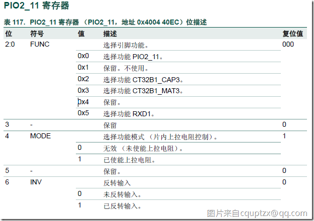
随意列举一个引脚寄存器的各位的表示,例如:PIO2_11
4.4IO引脚配置结构体初始化
IOCON_StructInit(&PIO_mode);
这里调用了IOCON_StructInit函数,
void IOCON_StructInit ( IOCON_PIO_CFG_Type *mode)
{
mode->type = 0x0;
mode->pinmode = IOCON_PIO_MODE_PULLUP;
mode->invert = IOCON_PIO_INV_NOT;
mode->pmode = IOCON_PIO_PMODE_DISABLE;
mode->od = IOCON_PIO_OD_DISABLE;
mode->drive = IOCON_PIO_DRV_2MA_12MA;
mode->ad = IOCON_PIO_AD_DIGITAL;
mode->sm = IOCON_PIO_SMODE_BYPASS;
mode->cd = IOCON_PIO_CLKDIV_0;
}
可以看到,这里只是给空的IO引脚配置结构体赋值(相当于上电复位).
4.5用引脚寄存器 给引脚配置结构体赋值,设置引脚为TXD、RXD.
/* 设置引脚为TXD、RXD功能 */
PIO_mode.type = TEST_UART_RXD;
IOCON_SetFunc(&PIO_mode);
PIO_mode.type = TEST_UART_TXD;
IOCON_SetFunc(&PIO_mode);
可以看到通过给IO引脚配置寄存器结构体赋值累配置为TXD或者RXD
这里调用了IOCON_SetFunc函数
void IOCON_SetFunc ( IOCON_PIO_CFG_Type *mode)
{
uint32_t offset;
uint32_t func;
uint32_t tmp;
uint32_t *p = (uint32_t *)&LPC_IOCON->PIO2_28;
CHECK_PARAM( PARAM_IOCON_PIO_TYPE(mode->type) );
CHECK_PARAM( PARAM_IOCON_PIO_MODE(mode->pinmode));
CHECK_PARAM( PARAM_IOCON_PIO_DRV(mode->drive) );
CHECK_PARAM( PARAM_IOCON_PIO_AD(mode->ad) );
CHECK_PARAM( PARAM_IOCON_PIO_OD(mode->od));
CHECK_PARAM( PARAM_IOCON_PIO_INV(mode->invert) );
CHECK_PARAM( PARAM_IOCON_PIO_SMODE(mode->sm));
CHECK_PARAM( PARAM_IOCON_PIO_CLKDIV(mode->cd));
offset = (mode->type >> 6);
func = (mode->type & 0xf);
if(offset == 0x24 || offset == 0x25){ //0x90, 0x94 right shift 2 bit
tmp = (uint32_t)(func|(mode->pmode)|(mode->od)|(mode->invert)|(mode->sm)|(mode->cd));
}else{
tmp = (uint32_t)(func|(mode->pinmode)|(mode->drive)|(mode->ad)|(mode->od)|(mode->invert)|(mode->sm)|(mode->cd));
}
*(uint32_t *)(p + offset) = tmp;
}
对应于IO引脚配置寄存器的Func域.
4.6根据串口号来:复位外设,配置外设时钟,设置分频系数.
#if (UART_PORT == 0) /* 打开UART时钟模块 */
SYS_ResetPeripheral(SYS_PRESETCTRL_UART0_RST,DISABLE); //复位外设
SYS_ConfigAHBCLK(SYS_AHBCLKCTRL_UART0, ENABLE); //外设时钟配置
SYS_SetUART0ClockDiv(1); //设置分频系数
#endif
#if (UART_PORT == 1)
SYS_ResetPeripheral(SYS_PRESETCTRL_UART1_RST,DISABLE);
SYS_ConfigAHBCLK(SYS_AHBCLKCTRL_UART1, ENABLE);
SYS_SetUART1ClockDiv(1);
#endif
可以看到这里有三个主要步骤:复位外设,外设时钟配置,设置分频系数.
调用了SYS_ResetPeripheral函数,
/**
* @brief Reset peripheral复位外设.
*
* @param RSTBlock: Peripheral type 外设类型.
* @param CmdState: Command State. 命令状态
* This parameter can be DISABLE or ENABLE.
* @retval None.
*/
void SYS_ResetPeripheral(uint32_t RSTBlock, FunctionalState CmdState)
{
if (CmdState == ENABLE){
LPC_SYSCON->PRESETCTRL &= ~(RSTBlock);
} else {
LPC_SYSCON->PRESETCTRL |= (RSTBlock);
}
}
调用了SYS_ConfigAHBCLK函数,
/**
* @brief Disable or enable system and peripheral clock.
*
* @param AHBClk_Type: AHB clock type.外设时钟类型
* @param CmdState: Enable or disable the clock for System or
* peripheral blocks. 命令状态
* This parameter can be ENABLE or DISABLE.
* @retval None.
*/
void SYS_ConfigAHBCLK(uint32_t AHBClk_Type, FunctionalState CmdState)
{
if(CmdState) LPC_SYSCON->SYSAHBCLKCTRL |= AHBClk_Type;
else LPC_SYSCON->SYSAHBCLKCTRL &= ~(AHBClk_Type);
}
调用了SYS_SetUART0ClockDiv函数
/**
* @brief Set clock divider value for UART0.
*
* @param DivNum: The divider for UART0 clock.
* This parameter can be one of the following values:
* @arg 0: disable UART0
* @arg 1~255: Divided by this number
* @retval None.
* FUART0 = FMainClk / DivNum
*/
void SYS_SetUART0ClockDiv(uint32_t DivNum)
{
LPC_SYSCON->UART0CLKDIV = (DivNum & 0xFF);
}
DivNum & 0xFF ,1 与0xFF,还是为1.
4.7复位串口,
UART_Init(TEST_UART); //初始化串口//复位串口 /* 使能UART */
调用了UART_Init函数
/*
* @brief Initializes the UARTx peripheral.初始化串口外设.//初始化可以理解为复位么?
* @param UARTx UART peripheral selected, should be LPC_UART0, LPC_UART1.选择的串口(LPC_UART0或者LPC_UART1)
* @return None
*/
void UART_Init(LPC_UART_TypeDef *UARTx)
{
volatile uint32_t tmp; //volatile关键字的作用是防止编译器对词条语句进行优化.
CHECK_PARAM(PARAM_UARTx(UARTx));
UARTx->FDR = 0x10; //set to default value: 0x10 小数分频寄存器。生成波特率分频器的时钟输入
/* Empty the registers */
UARTx->FCR = ( UART_FCR_FIFO_EN | UART_FCR_RX_RS | UART_FCR_TX_RS);
while (UARTx->LSR & UART_LS_RX_DATA_READY){
tmp = UARTx->RBR; // Dummy reading
}
UARTx->TER = UART_TER_TXEN;
while (!(UARTx->LSR & UART_LS_TX_EMPTY)); // Wait for current transmit complete
UARTx->TER = 0; // Disable Tx
UARTx->IER = 0; // Disable interrupt
UARTx->LCR = 0; // Set LCR to default state
UARTx->ACR = 0; // Set ACR to default state
if (UARTx == LPC_UART0){
#ifdef _MODEM
UARTx->MCR = 0; // Set Modem Control to default state
tmp = UARTx->MSR; // Dummy Reading to Clear Status
#endif
#ifdef _RS485
UARTx->RS485CTRL = 0; // Set RS485 control to default state
UARTx->ADRMATCH = 0; // Set RS485 addr match to default state
UARTx->RS485DLY = 0; // Set RS485 delay timer to default state
#endif
}
#ifdef _IRDA
else{
UARTx->ICR = 0; // Set IrDA to default state
}
#endif
tmp = UARTx->LSR; // Dummy reading
tmp = uart_get_num(UARTx);
UART_Configration[tmp].baudrate = 0;
UART_Configration[tmp].databits = UART_CFG_DATABIT_8;
UART_Configration[tmp].stopbits = UART_CFG_STOPBIT_1;
UART_Configration[tmp].parity = UART_CFG_PARITY_NONE;
UART_Configration[tmp].fifolevel = UART_CFG_FIFOTRG_1;
UART_Configration[tmp].fifodma = UART_CFG_DMAMODE_DISABLE;
UART_Configration[tmp].txdbreak = UART_CFG_TXDBREAK_DISABLE;
}
4.8将生成的空结构体作为现在要用的串口的配置结构体.
/* 将参数赋值给UARTConfigStruct */
UART_GetConfig(TEST_UART, &UARTConfigStruct); //将生成的空结构体作为现在要用的串口的配置结构体.
/*
* @brief Get configuration the UARTx according to the specified parameters in the UART_CFG_Type.
* 将生成的空结构体作为现在要用的串口的配置结构体.
* @param UARTx UART peripheral selected, should be LPC_UART0, LPC_UART1.
* @param config UART_ConfigStruct Pointer to a UART_CFG_Type structure
* that contains the configuration information for the specified UART periphera.
* @return None
*/
void UART_GetConfig(LPC_UART_TypeDef *UARTx, UART_CFG_Type *config)
{
uint32_t tmp;
CHECK_PARAM(PARAM_UARTx(UARTx));
tmp = uart_get_num(UARTx);
*config = UART_Configration[tmp];
}
4.9串口配置结构体成员赋值.
/* 设置为8位数据 */
UARTConfigStruct.databits = UART_CFG_DATABIT_8; //现在配置结构体:设置为8位数据.
4.10对结构体成员赋值.更新配置参数
/* 更新配置参数 */
UART_SetConfig(TEST_UART, &UARTConfigStruct); //对结构体成员赋值.
/*
* @brief Config the UARTx according to the specified parameters in the UART_CFG_Type.
* @param UARTx UART peripheral selected, should be LPC_UART0, LPC_UART1.
* @param config UART_ConfigStruct Pointer to a UART_CFG_Type structure
* that contains the configuration information for the specified UART periphera.
* @return None
*/
void UART_SetConfig(LPC_UART_TypeDef *UARTx, UART_CFG_Type *config)
{
uint8_t tmp;
CHECK_PARAM(PARAM_UARTx(UARTx));
CHECK_PARAM(PARAM_UART_DATABIT(config->databits));
CHECK_PARAM(PARAM_UART_PARITY(config->parity));
CHECK_PARAM(PARAM_UART_STOPBIT(config->stopbits));
CHECK_PARAM(PARAM_UART_FIFO_LEVEL(config->fifolevel));
CHECK_PARAM(PARAM_UART_FIFO_DMA(config->fifodma));
tmp = uart_get_num(UARTx);
if(UART_Configration[tmp].baudrate != (*config).baudrate){
uart_set_divisors(UARTx, (config->baudrate));
UART_Configration[tmp].baudrate = (*config).baudrate;
}
UARTx->LCR = (((config->databits)|(config->parity)|(config->stopbits)|\
(config->txdbreak)) & UART_LCR_BITMASK);
UARTx->FCR = ((UART_FCR_FIFO_EN | (config->fifodma)|(config->fifolevel))&\
UART_FCR_BITMASK);
UART_Configration[tmp].databits = (*config).databits;
UART_Configration[tmp].stopbits = (*config).stopbits;
UART_Configration[tmp].parity = (*config).parity;
UART_Configration[tmp].txdbreak = (*config).txdbreak;
UART_Configration[tmp].fifolevel = (*config).fifolevel;
UART_Configration[tmp].fifodma = (*config).fifodma;
}
4.11串口发送使能
/* 使能发送功能 */
UART_ConfigTXD(TEST_UART, ENABLE); //
/**
* @brief Enable/Disable transmission on UART TxD pin使能某个串口的发送引脚
* @param UARTx UART peripheral selected, should be LPC_UART0, LPC_UART1
* @param NewState New State of Tx transmission function, should be:
* - ENABLE: Enable this function
* - DISABLE: Disable this function
* @return none
*/
void UART_ConfigTXD(LPC_UART_TypeDef *UARTx, FunctionalState NewState)
{
CHECK_PARAM(PARAM_UARTx(UARTx));
if (NewState == ENABLE) {
UARTx->TER |= UART_TER_TXEN; //相或置一 x|1 = 1
}else{
UARTx->TER &= (~UART_TER_TXEN) & UART_TER_BITMASK; //(~1)&0x80 = 0.零和任意数相与为0;
}
}
2013年4月1日 0:
5.串口发送字节数据uartSendByte
/*********************************************************************************************************
115 ** Function name: uartSendByte
116 ** Descriptions: 向串口发送字节数据,并等待数据发送完成,使用查询方式
117 ** input parameters: ucDat: 要发送的数据
118 ** output parameters: 无
119 ** Returned value: 无
120 *********************************************************************************************************/
121 void uartSendByte (uint8_t ucDat)
122 {
123 UART_Send(TEST_UART, &ucDat, 1, UART_BLOKING_TIMEOUT); /* 写入数据 */
124 while (!(UART_GetLineStatus(TEST_UART) & UART_LS_TX_EMPTY_ALL)); /* 等待数据发送完毕 */
125 }
可以看到,串口发送字节数据调用了UART_Send函数,
这个函数有三个参数:
- 发送数据的串口
- 发送的数据内容(指针)
- 发送到数据长度
返回 已经发送到字节数.
/*
* @brief Send a block of data via UART peripheral通过串口外设发送一块数据.
* @param UARTx Selected UART used to send data, should be LPC_UART0, LPC_UART1.串口号
* @param txbuf Pointer to Transmit buffer数据指针
* @param buflen Length of Transmit buffer, a multiple of 16 is better.发送数据的长度
* 16 is the best because the FIFO number is 16.
* @param timeout UART_process_time_delay definition 处理时延
* @return Number of bytes sent.返回已发送的bytes数.
*/
uint32_t UART_Send(LPC_UART_TypeDef *UARTx, uint8_t *txbuf, uint32_t buflen,\
uint32_t timeout)
{
uint32_t bToSend, bSent, timeOut, fifo_cnt;
uint8_t *pChar = txbuf;
CHECK_PARAM(PARAM_UARTx(UARTx));
CHECK_PARAM(PARAM_UART_PROCESS_DELAY(timeout));
bToSend = buflen;
bSent = 0;
while (bToSend){
timeOut = timeout;
// Wait for THR empty with timeout
while (!(UARTx->LSR & UART_LS_TX_EMPTY)) {
if (timeOut == 0) break;
timeOut--;
}
if(timeOut == 0) break; // Time out!
fifo_cnt = UART_TX_FIFO_SIZE;
while (fifo_cnt && bToSend){
UARTx->THR = ((*pChar++) & UART_THR_MASKBIT);
fifo_cnt--;
bToSend--;
bSent++;
}
}
return bSent;
}
6.串口发送字符串
127 /*********************************************************************************************************
128 ** Function name: uartSendStr
129 ** Descriptions: 向串口发送字符串
130 ** input parameters: pucStr: 要发送的字符串指针
131 ** output parameters: 无
132 ** Returned value: 无
133 *********************************************************************************************************/
134 void uartSendStr (char *pcStr)
135 {
136 while (1){
137 if (*pcStr == '\0') break; /* 遇到结束符,退出 */
138 uartSendByte(*pcStr++);
139 }
140 }
串口发送字符串函数就是调用了串口发送字节函数.
那么归纳起来, 发送字符串--->发送字节-->UART_Send
7.主函数
142 /*********************************************************************************************************
143 ** Function name: main
144 ** Descriptions: 主函数(函数入口)
145 ** 串口参数: UART波特率9600、8个数据位、1个停止位、无奇偶校验位
146 ** 跳线连接: P0.8(RXD1)、P0.9(TXD1)(若使用UART0则连接P0.1(RXD0)和P0.2(TXD0))通过232电平
147 ** 转换芯片分别连接到PC机串口的TXD、RXD;
148 ** 操作方法: 打开串口调试软件,运行程序,下位机等待PC向串口发送字符'a'或'A',观察显示窗口
149 ** 现 象: 串口调试软件显示当前波特率
150 ** input parameters: 无
151 ** output parameters: 无
152 ** Returned value: 无
153 *********************************************************************************************************/
154 int main (void)
155 {uartInit(); /* 串口初始化 */
164
165 while (1) {
166
167
168 /* 启动自动波特率 */
169 UART_StartAutoBaud(TEST_UART, UART_CFG_AUTOBAUD_MODE0, UART_CFG_ABRESTART_ENABLE);
170
171 /* 等待计算波特率完成 */
172 while (TEST_UART->ACR & UART_ACR_START) // (ACR=1) 与 (UART_ACR_START=1) //在自动波特率功能结束后,系统会清除UART_ACR_START此位。
173 {
179
180 }
181
182 /* 读取除数锁存器 */
183 //在LCR的DLAB=1的前提下读取DLL,DLM,然后清除LCR的DLAB
184 TEST_UART->LCR |= UART_LCR_DLAB_EN;
185 GucDll = TEST_UART->DLL;
186 GucDlm = TEST_UART->DLM;
187 TEST_UART->LCR &= ~UART_LCR_DLAB_EN;
188
189 /* 波特率计算,存在一定的误差 */
190 //波特率计算公式: UARTbaudrate=PCLK/(16*(256*DLM+DLL)*(1+DivAddVal/MulVal))
191 GulBaud = (MainClock / (16 * (256 * GucDlm + GucDll)));
192
193 /* 处理要发送的数据,然后向串口发送字符串 */
194 //函数原型int sprintf( char *buffer, const char *format [, argument] ... );
195 // (1)格式化字符串上。
196 // (2)字符/Ascii 码对照
197 // (3)连接字符串
198 //三个参数,保存数据的目的指针,格式,数据源指针. 将数据源格式化保存到数据目的指针处.
199 sprintf(GcStr, " Baud is %4d bps \n", GulBaud);
200 uartSendStr(GcStr);
201
202 }
203 }
7.1主函数主要流程
- 1.串口初始化uartInit();
- 2.启动自动波特率UART_StartAutoBaud
- 3.等待
- 4.读除数锁存器
- 5.计算波特率
- 6.处理待发送字符串
- 7.根据波特率发送字符串
7.2串口初始化
串口初始化已经在上面讲过了,见"4.串口初始化过程"部分
7.3启动自动波特率
/*
* @brief Start Auto Baudrate activity启动自动波特率活动:配置
* @param UARTx UART peripheral selected, should be LPC_UART0, LPC_UART1
* @param mode UART_auto_baudrate_mode_type 串口自动波特率模式类型
* @param restart UART_auto_baudrate_restart_type definitions串口自动波特率复位类型
* @return none
*/
void UART_StartAutoBaud(LPC_UART_TypeDef *UARTx, uint8_t mode, uint8_t restart)
{
CHECK_PARAM(PARAM_UARTx(UARTx));
CHECK_PARAM(PARAM_UART_AB_MODE(mode));
CHECK_PARAM(PARAM_UART_AB_RESTART(restart));
// Clear DLL and DLM value
//在UART_LCR_DLAB_EN置一的前提下,清除DLL和DLM,LCR.
UARTx->LCR |= UART_LCR_DLAB_EN; // 按位或置一,UART_LCR_DLAB_EN 串口线路控制器除数锁存器访问位 置一
UARTx->DLL = 0; //DLL 除数锁存器 最低有效字节.
UARTx->DLM = 0; //DLM 除数锁存器最高有效字节.
UARTx->LCR &= ~UART_LCR_DLAB_EN;//LCR 决定要发送或接收的数据字符的格式.清除LCR=0.
// FDR value must be reset to default value
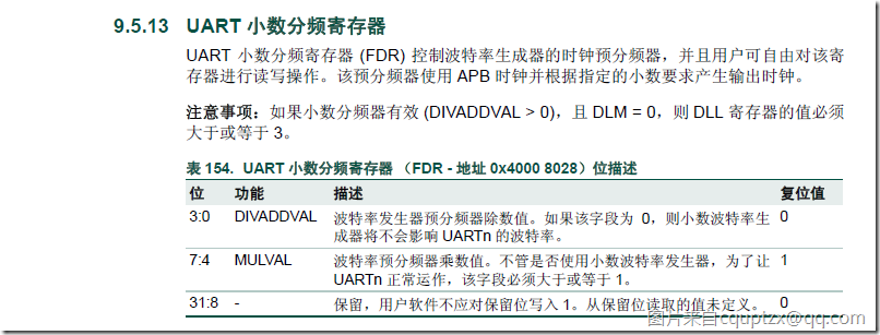
UARTx->FDR = 0x10;//FDR=xxxx xxxx MULVAL DIVADDVAL;这里最后四位为0,说明禁用了小数分频;如果DIVADDVAL为0,那么小数分频器将被禁用,并且不会对时钟进行分频。
UARTx->ACR = (UART_ACR_START | (mode) | (restart));//自动波特率控制器ACR=UART_ACR_START 或 mode 或 重启动.如果最后是1,那么就自动波特率启动.
可以看到,自动波特率设置 主要是
- 1.清除除数锁存器
- 2.禁止小数分频器
- 3.启动自动波特率位.
7.4等待系统清除UART_ACR_START
171 /* 等待计算波特率完成 */
172 while (TEST_UART->ACR & UART_ACR_START) // (ACR=1) 与 (UART_ACR_START=1) //在自动波特率功能结束后,系统会清除UART_ACR_START此位。
只要有1个0,那么就跳出循环.
为0的意思就是自动波特率停止.
7.5读除数锁存器
/* 读取除数锁存器 */
183 //在LCR的DLAB=1的前提下读取DLL,DLM,然后清除LCR的DLAB
184 TEST_UART->LCR |= UART_LCR_DLAB_EN;
185 GucDll = TEST_UART->DLL;
186 GucDlm = TEST_UART->DLM;
187 TEST_UART->LCR &= ~UART_LCR_DLAB_EN;
读除数锁存器的内容的前提是DLAB=1,读完后清零.
7.6计算波特率
/* 波特率计算,存在一定的误差 */
190 //波特率计算公式: UARTbaudrate=PCLK/(16*(256*DLM+DLL)*(1+DivAddVal/MulVal))
191 GulBaud = (MainClock / (16 * (256 * GucDlm + GucDll)));
计算波特率就一个公式:
7.7处理带发送的字符串
这里将要显示的字符串进行处理,显示波特率参数.
/* 处理要发送的数据,然后向串口发送字符串 */
194 //函数原型int sprintf( char *buffer, const char *format [, argument] ... );
195 // (1)格式化字符串上。
196 // (2)字符/Ascii 码对照
197 // (3)连接字符串
198 //三个参数,保存数据的目的指针,格式,数据源指针. 将数据源格式化保存到数据目的指针处.
199 sprintf(GcStr, " Baud is %4d bps \n", GulBaud);
主要是sprintf函数的使用.
我们这里使用的是,将格式化后的字符串保存到GcStr中.
用参数GulBaud 填充%4d,那么源字符串 "Baud is %4d bps\n",经过参数GulBaud填充后,变成了大约9600左右的数据.
最后输出
Baud is 9615 bps
7.8串口根据波特率发送数据
uartSendStr(GcStr);
uartSendStr上面已经讲过了,见"6.串口发送字符串"
整理时间
2013年4月1日 13:40:22
