【Game Engine Architecture 11】
1、three most-common techniques used in modern game engines.
1)Cel Animation
2)Rigid Hierarchical Animation
3)Per-Vertex Animation and Morph Targets
2、Cel Animation
The precursor to all game animation techniques is known as traditional animation, or hand-drawn animation. This is the technique used in the earliest animated cartoons.
Cel animation is a specific type of traditional animation. A cel is a transparent sheet of plastic on which images can be painted or drawn.
The electronic equivalent to cel animation is a technology known as sprite animation.

3、Rigid Hierarchical Animation,刚体层次动画 / 刚体动画。
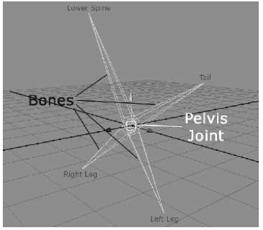
a character is modeled as a collection of rigid pieces. A typical breakdown for a humanoid character might be pelvis(盆骨), torso(躯干), upper arms, lower arms, upper legs, lower legs, hands, feet and head.
A typical hierarchy has the pelvis at the root, with the torso and upper legs as its immediate children and so on as shown below:

The big problem with the rigid hierarchy technique is that the behavior of the character’s body is often not very pleasing due to “cracking” at the joints. This is illustrated in Figure 12.2.

4、Per-Vertex Animation and Morph Targets
per vertex animation is a data-intensive technique, since time-varying motion information must be stored for each vertex of the mesh. For this reason, it has little application to real-time games.
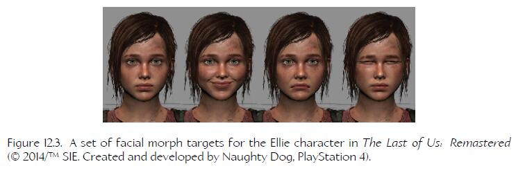
morph target animation is used in some real-time games. Animations are produced by blending between two or more of these fixed poses at runtime. The morph target technique is often used for facial animation, because the human face is an extremely complex piece of anatomy, driven by roughly 50 muscles.
As computing power continues to increase, some studios are using jointed facial rigs containing hundreds of joints as an alternative to morph targets. Other studios combine the two techniques, using jointed rigs to achieve the primary pose of the face and then applying small tweaks via morph targets.
顽皮狗的《最后生还者》中,Ellie的面部动画使用提 morph target。
5、Skinned Animation,蒙皮动画。
In skinned animation, a skeleton is constructed from rigid “bones,” just as in rigid hierarchical animation. However, instead of rendering the rigid pieces on-screen, they remain hidden. A smooth continuous triangle mesh called a skin is bound to the joints of the skeleton; its vertices track the movements of the joints. Each vertex of the skin mesh can be weighted to multiple joints, so the skin can stretch in a natural way as the joints move.
Rigid Hierarchical Animation 直接渲染 rigid piece,而 Skinned Animation 渲染的是 skin mesh。
6、Skeletons
In the game industry, we often use the terms “joint” and “bone” interchangeably, but the term bone is actually a misnomer. Technically speaking, the joints are the objects that are directly manipulated by the animator, while the bones are simply
the empty spaces between the joints.
7、SRT Transformations
SRT transforms are widely used in computer animation because of their smaller size (eight floats for uniform scale, or ten floats for nonuniform scale, as opposed to the 12 floating-point numbers needed for a 4 x 3 matrix) and their ability to be easily interpolatefd.

8、Representing a Skeleton in Memory
struct Joint
{
    Matrix4x3 m_invBindPos;

    const char* m_name; // human-readable joint name
    U8 m_iParent; // parent index or 0xFF if root
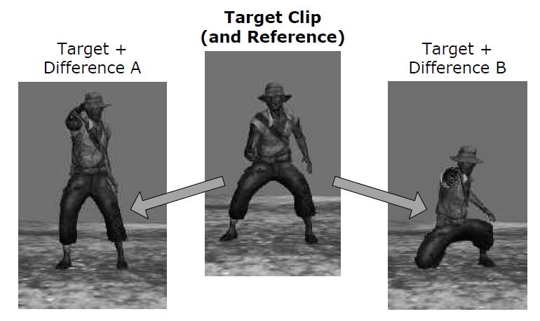
};

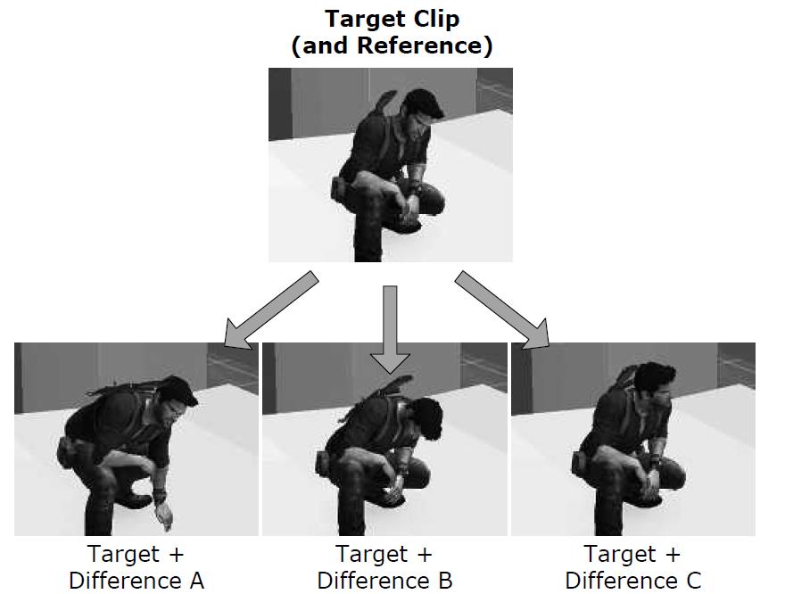
struct Skeleton
{
    U32 m_jointCount; // number of joints
    Joint* m_aJoint; // array of joints
};
9、Poses
The pose of a joint is defined as the joint’s position, orientation and scale, relative to some frame of reference. A joint pose is usually represented by a 4x4 or 4x3 matrix, or by an SRT data structure (scale, quaternion rotation and vector translation). The pose of a skeleton is just the set of all of its joints’ poses and is normally represented as a simple array of SRTs.
skeleton 的姿势就是其内所有 joint 的姿势 。
10、Bind Pose
This is the pose of the 3D mesh prior to being bound to the skeleton. 3D mesh 绑定前的姿势。
The bind pose is also called T-pose. This particular stance is chosen because it keeps the limbs away from the body and each other, making the process of binding the vertices to the joints easier.
11、Local Poses
A joint’s pose is most often specified relative to its parent joint. Local poses are almost always stored in SRT format.
many 3D authoring packages like Maya represent joints as small spheres. However, a joint has a rotation and a scale, not just a translation, so this visualization can be a bit misleading.
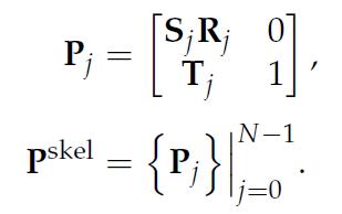
The pose of an entire skeleton P^skel can be written as the set of all poses Pj, where j ranges from 0 to N-1:
12、Representing a Joint Pose in Memory
struct JointPose
{
    Quaternion m_rot; // R
    Vector3 m_trans; // T
    F32 m_scale; // S (uniform scale only)
};

struct JointPose
{
    Quaternion m_rot; // R
    Vector4 m_trans; // T
    Vector4 m_scale; // S
};

struct SkeletonPose
{
    Skeleton* m_pSkeleton; // skeleton + num joints
    JointPose* m_aLocalPose; // local joint poses
};
13、Representing a Global Pose in Memory
struct SkeletonPose
{
    Skeleton* m_pSkeleton; // skeleton + num joints
    JointPose* m_aLocalPose; // local joint poses
    Matrix44* m_aGlobalPose; // global joint poses
};
13.1、The Joint Pose as a Change of Basis
when the joint pose transform Pj is applied to a point or vector that is expressed in the coordinate system of the joint j, the result is that same point or vector expressed in the space of the parent joint.
Pj 是关节 j 的Pose矩阵。Pj 可以将将 j 坐标下的点转移到 P(j) 下。
14、Clips
game animations are almost never created as long, contiguous sequences of frames. Instead, a game character’s movement must be broken down into a large number of fine-grained motions. We call these individual motions animation clips, or sometimes just animations.
The term FMV applies to sequences that have been prerendered to an MP4, WMV or other type of movie file and are played back at runtime by the engine’s full-screen movie player.
quick time event (QTE). In a QTE, the player must hit a button at the right moment during an otherwise noninteractive sequence in order to see the success animation and proceed;
15、Frames, Samples and Looping Clips
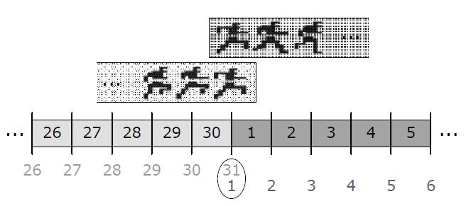
• If a clip is non-looping, an N-frame animation will have N + 1 unique samples.
• If a clip is looping, then the last sample is redundant, so an N-frame animation will have N unique samples.
16、A Simple Animation Data Format
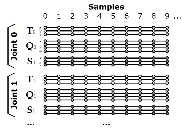
struct AnimationSample
{
    JointPose* m_aJointPose; // array of joint poses
};

struct AnimationClip
{
    Skeleton* m_pSkeleton;
    F32 m_framesPerSecond;
    U32 m_frameCount;
    AnimationSample* m_aSamples; // array of samples
    bool m_isLooping;
};
17、Relationship between Meshes, Skeletons and Clips
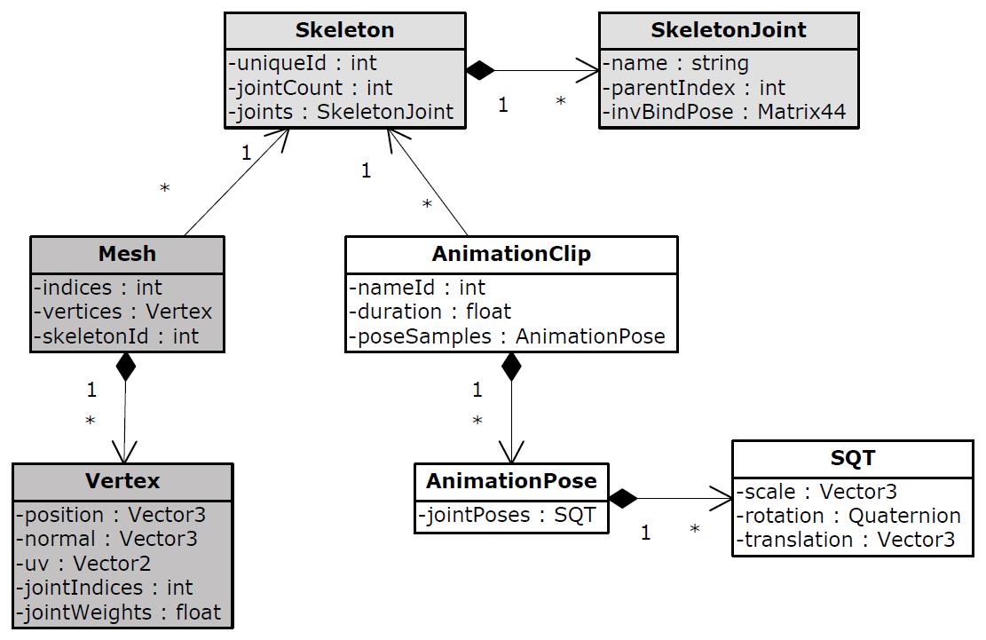
the skins are attached to the skeleton but don’t have any relationship with the animation clips. Likewise, the clips are targeted at a particular skeleton, but they have no “knowledge” of the skin meshes.

To provide the illusion of many different types of characters, it is usually better to create multiple meshes skinned to the same skeleton when possible, so that all of the characters can share a single set of animations.
18、Per-Vertex Skinning Information
Usually a game engine imposes an upper limit on the number of joints to which a single vertex can be bound. A four-joint limit is typical for a number of reasons. First, four 8-bit joint indices can be packed into a 32-bit word, which is convenient. Also, while it’s pretty easy to see a difference in quality between a two-, three- and even a four-joint-per-vertex model, most people cannot see a quality difference as the number of joints per vertex is increased beyond four.
struct SkinnedVertex
{
    float m_position[3]; // (Px, Py, Pz)
    float m_normal[3]; // (Nx, Ny, Nz)
    float m_u, m_v; // texture coords (u,v)
    U8 m_jointIndex[4]; // joint indices
    float m_jointWeight[3]; // joint weights (last weight omitted)
};
19、The Mathematics of Skinning
we would like to find a matrix that can transform the vertices of the mesh from their original positions (in bind pose) into new positions that correspond to the current pose of the skeleton. We shall call such a matrix a skinning matrix.
skinning matrix 将vetex从 bind pose 转换到 current pos。
the position of a skinned vertex is specified in model space. This is true whether its skeleton is in bind pose or in any other pose.
bind pose、any pose 下,vertex 坐标系都是 model space。
20、Simple Example: One-Jointed Skeleton
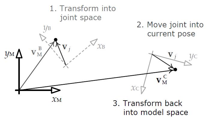


The combined matrix Kj is known as a skinning matrix.
21、Incorporating the Model-to-World Transform
![]()
a technique known as animation instancing that is sometimes used for animating large crowds of characters. In this case we need to keep the model-to-world transforms separate so that we can share a single matrix palette across all characters in the crowd.
当使用 animation instancing 的时候,Kj 不会与 M(M->W)结合。
22、LERP Blending
混合两个 skeleton pose 等于混合其下各个 joint。


interpolating matrices directly is not practical. This is one of the reasons why local poses are usually expressed in SRT format.
23、Types of Cross-Fades
• Smooth transition.

• Frozen transition.
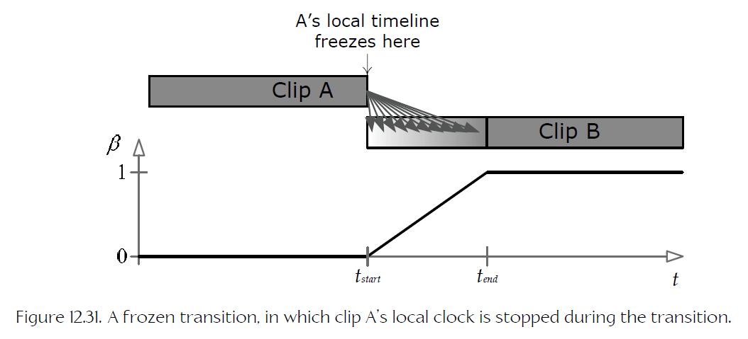
Bezier ease-in、ease-out 公式:

24、Directional Locomotion
1)pivotal movement,轴向移动
2)target movement,靶向移动
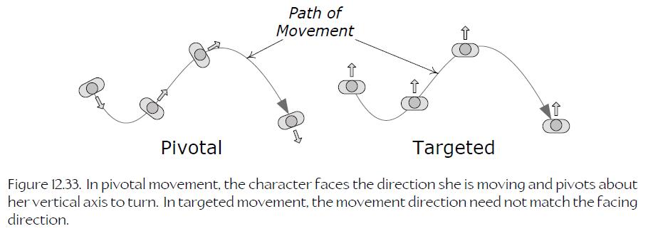
25、Targeted Movement
the animator authors three separate looping :one moving forward, one strafing to the left, and one strafing to the right. I’ll call these directional locomotion clips.
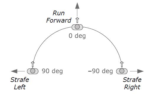
26、Pivotal Movement
To implement pivotal movement, we can simply play the forward locomotion loop while rotating the entire character.
pivotal movemnt,简单的情况,播放一个前向动画即可。
Pivotal movement looks more natural if the character’s body doesn’t remain bolt upright when it is turning—real humans tend to lean into their turns a
little bit. A more natural-looking result can be achieved by animating three variations on the basic forward walk or run—one going perfectly straight, one making an extreme left turn and one making an extreme right turn. We can then LERP-blend between the straight clip and the extreme left turn clip to implement any desired lean angle.
更为真实的处理为,类似 target movement,提供三个动画,一个前身,一个左倾,一个右倾。
27、Simple Two-Dimensional LERP Blending
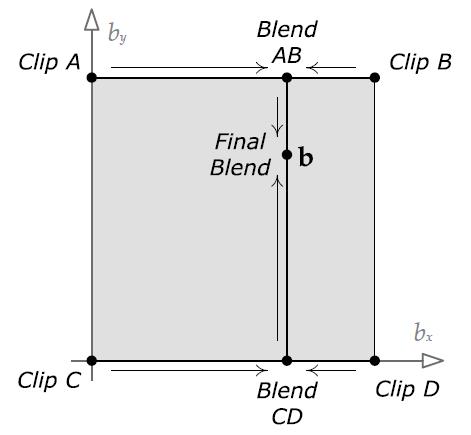
28、Generalized Two-Dimensional LERP Blending
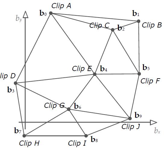
![]()
FIFA soccer by EA Sports in Vancouver, implemented within their proprietary “ANT” animation framework.
29、Parital-Skeleton Blending
30、Additive Blending
31、Mathematical Formulation
So given the source pose Sj and the reference pose Rj for any joint j in the skeleton, we can define the difference pose Dj at that joint as follows.
![]()
31.1、Additive Blending
Simple example, imagine a target animation in which the character’s left arm is bent at a 90 degree angle. If we add a difference animation that also rotates the elbow by 90 degrees, then the net effect would be to rotate the arm by 90 + 90 = 180 degrees. This would cause the lower arm to interpenetrate the upper arm—not a comfortable position for most individuals!
32、Stance Variation。Additive Blending的应用之一。
33、Locomotion Noise,运动噪声。Additive Blending 的应用之二。
Real humans don’t run exactly the same way with every footfall—there is variation in their movement over time.
34、animation Post-Processing
Once a skeleton has been posed by one or more animation clips and the results have been blended together using linear interpolation or additive blending, it is often necessary to modify the pose prior to rendering the character. This is called animation post-processing.
35、Procedural Animations,animation post-processing 的一种。
1)animator只需要制作汽车往前开的动画,procedural animation 将 quaternion 附加给 front wheel、steering wheel。
2)bushes sway、aside 效果。将 bushes 动画制作为骨骼动画,给他们的 root 施加一个 quaternion。
35.1、Inverse Kinematics
regular animation clip is an example of forward kinematics (FK). In forward kinematics, the input is a set of local joint poses, and the output is a global pose and a skinning matrix for each joint.
Inverse kinematics goes in the other direction: The input is the desired global pose of a single joint, which is known as the end effector. We solve for the local poses of other joints in the skeleton that will bring the end effector to the desired location.
36、Quantization

U32 CompressUnitFloatRL(F32 unitFloat, U32 nBits)
{
    // Determine the number of intervals based on the
    // number of output bits we've been asked to produce.
    U32 nIntervals = 1u << nBits;

    // Scale the input value from the range [0, 1] into
    // the range [0, nIntervals - 1]. We subtract one
    // interval because we want the largest output value
    // to fit into nBits bits.
    F32 scaled = unitFloat * (F32)(nIntervals - 1u);

    // Finally, round to the nearest interval center. We
    // do this by adding 0.5f and then truncating to the
    // next-lowest interval index (by casting to U32).
    U32 rounded = (U32)(scaled + 0.5f);

    // Guard against invalid input values.
    if (rounded > nIntervals - 1u)
        rounded = nIntervals - 1u;

    return rounded;
}
To handle arbitrary input values in the range [min, max], we can use these routines:

U32 CompressFloatRL(F32 value, F32 min, F32 max, U32 nBits)
{
    F32 unitFloat = (value - min) / (max - min);
    U32 quantized = CompressUnitFloatRL(unitFloat, nBits);

    return quantized;
}

F32 DecompressFloatRL(U32 quantized, F32 min, F32 max, U32 nBits)
{
    F32 unitFloat = DecompressUnitFloatRL(quantized, nBits);
    F32 value = min + (unitFloat * (max - min));

    return value;
}
37、Curve-Based Compression
One of the most powerful, easiest-to-use and best-thought-out animation APIs I’ve ever worked with is Granny, by Rad Game Tools. Granny stores animations not as a regularly spaced sequence of pose samples but as a collection of nth-order, nonuniform, nonrational B-splines, describing the paths of a joint’s S, Q and T channels over
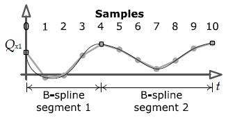

38、Blend Trees
An animation blend tree is an example of what is known in compiler theory as an expression tree or a syntax tree. The interior nodes of such a tree are operators, and the leaf nodes serve as the inputs to those operators.
39、Constraints
1)Attachments
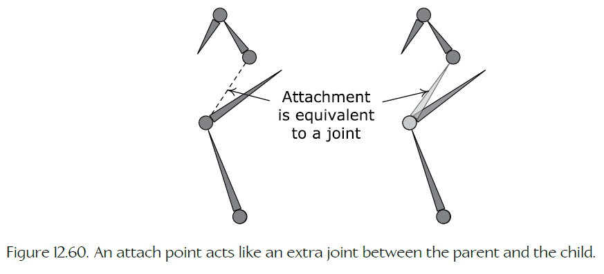
Such special joints that they can be ignored by the animation blending pipeline are sometimes called attach points.
attach point 是一种特殊的 joint。
2)Reference Locator
每个动画中分别记录一个统一挂点。
3)IK。
The joint whose position we are trying to correct is known as the end effector.
40、
