Table of Contents
3.1 Connected state uploading. 7
3.2 Initial state uploading steps. 8
1 Introduction
This
The a37 file, called S-Record file, made by Motorola, has a simple structure, whose description can be found here http://www.amelek.gda.pl/avr/uisp/srecord.htm
The Hitachi CPU is: H8/3687
2 Message format
2.1 Bit rate adjustment
|
Request |
0x00 0x00 0x00 … |
|
Response |
0x00 |
|
Request |
0x55 |
|
Response |
0xAA |
Continuously sending 0x00 to device is to adjust the bit rate, as the device doesn’t know the bit rate when powered on, it needs a 0x00 serial to learn the actual bit rate used in PC. Generally, PC uses 9600bps to send this serial, 3~20 bytes will be sent continuously before the device understands the bit rate. Once the device understands the bit rate, it will send back 0x00 as a response which asks PC to stop sending the serial bytes.
Once 0x00 is received from device, PC sends 0x55 and receives 0xAA, there is no reason for this.
2.2 Upload micro kernel
|
Request |
LengthH byte of micro kernel |
|
Response |
LengthH byte of micro kernel |
|
Request |
LengthL byte of micro kernel |
|
Response |
LengthL byte of micro kernel |
|
Request |
16*8 bytes of micro kernel content per frame |
|
Response |
Ack of the same bytes |
|
Repeat above 2 steps |
|
|
Request |
Rest bytes of micro kernel content |
|
Response |
Ack of the same bytes |
|
Response |
0xAA |
First send the length of micro kernel bytes to device so the device knows when to finish receiving. This sending is divided into two steps, one the sending the high byte of the length and get and ack; the other is sending the low byte of the length and get the ack.
Then begins sending the kernel, 16*8 bytes per frame, get the ack response to check it. Generally the last frame is less than 16*8 bytes, however as the device knows the total length, it will end receiving when receives the last byte, gives byte 0xAA as a response. Once the host receives 0xAA it is sure the kernel is uploaded successfully.
2.3 Increase baud rate
|
Request |
0x44 0x04 |
|
Response |
0x20 |
|
Request |
0x0F or 0x07 or something else |
One of the most important functionality of the micro kernel is to increase the baud rate. Here we just know 0x44 0x04 serial is to get the baud rate information of the device, once host gets the 0x20 response it will make some calculations which is not very clear. At last as a request to set the new baud rate, 0x0F is sent for 19200bps, if 38400bps is needed just send 0x07 instead.
2.4 Handshake
|
Request |
0x01 0x02 0x03 0x04 |
|
Response |
0x01 0x02 0x03 0x04 |
Handshake after increasing the bit rate, to make sure the communication works well.
2.5 Upload main kernel
|
Request |
Length of main kernel, high byte first |
|
Request |
All of the main kernel bytes one bye one |
Uploading main kernel is very simple, first send the length of the kernel so the device knows when to finish receiving; then send all the main kernel bytes, all in one frame or one by one are both OK.
No response here.
2.6 Get device properties
|
Request |
0x09 |
|
Response |
e.g.:0x01 0x00 0x80 0x00 0xCC 0x01 0x05 |
Send 0x09 to get device information, the response is a byte array indicates the device capacities. Here we don’t care its details; just follow the Hitachi Software to do this procedure.
2.7 Set unique device id
|
Request |
byte1 |
Byte1 (0x02~0xFF) depends on application host, if host can not get a unique device id, it will allocate a new unique id and assign it to the device, which usually occurs in the device initial state.
No response here, the following step is return check.
2.8 Return check
|
Request |
0x0A |
|
Response |
byte1 byte2 |
It is used to get the device type and unique device id. It is very useful to understand the device state: initial state or connected state and also useful to distinguish different devices when uploading.
Byte1 is the device type, currently it is 0xA3.
Byte2 is the unique id (generally from 0x02 to 0xFF), depends on application host. If in the initial state, host will allocate a unique id to identify the device and make it recognizable.
2.9 Write function
|
Request |
Length of write function, high byte first |
|
Request |
All the write function bytes |
|
Request |
Length of write function, high byte first |
|
Request |
Address for write function to be placed, here is it 0x01 0x80 |
Attention: 0x01 0x80 is the address of the function, main function will jump here to execute code if receives a write command from host.
No response. This message is often combined with other messages to provide a function together.
2.10Erase function
|
Request |
0x03 |
|
Request |
Length of erase function, high byte first |
|
Request |
All of erase function bytes |
0x03 is the command code. This message structure is different write function, don’t know why, and just follow it.
No response. This message is often combined with other messages to provide a function together.
2.11Unknown message
|
Request |
0x01 |
|
Response |
0x22 |
This exact request-response usually appears before uploading a main kernel, don’t know why, however, not all the main kernel uploading follows this message.
2.12Nested message
2.12.1 Erase flash
There are two combinations here, if it is for the first frame, the “with main kernel” will be used, otherwise the “without main kernel” will be used.
2.12.1.1 Erase flash without main kernel
|
Message |
ERASE FUNCTION MESSAGE |
|
Request |
EBR(5 bytes) |
|
Response |
0x24 |
EBR indicates which blocks of flash will be erased, we just follow Hitachi Software. All of the value lines are:
0x00, 0x00, 0x04, 0x00, 0x01
0x04, 0x00, 0x08, 0x00, 0x02
0x08, 0x00, 0x0C, 0x00, 0x04
0x0C, 0x00, 0x10, 0x00, 0x08
0x10, 0x00, 0x80, 0x00, 0x10
0x80, 0x00, 0xC0, 0x00, 0x20
0xC0, 0x00, 0xE0, 0x00, 0x40
If succeed, 0x24 will be send to host as a response.
2.12.1.2 Erase flash with main kernel
This message can also be combined with main kernel.
|
Message |
UPLOAD MAIN KERNEL MESSAGE |
|
Message |
ERASE FLASH MESSAGE |
Both of the two combinations are used in Hitachi Software.
2.12.2 Write flash
There are also two combinations here, if it is for the first frame, the “with main kernel” will be used, otherwise the “without main kernel” will be used.
2.12.2.1 Write flash without main kernel
|
Request |
0x22 |
|
Request |
1 byte length of data to be written |
|
Request |
Address to be written. Here it is 0x00 0x00 |
|
Message |
WRITE FUNCTION MESSAGE |
|
Request |
All bytes of the data to be written |
|
Response |
0x00 |
This message is generally used for the first block of the a37 file uploading; length is no more than 256.
2.12.2.2 Write flash with main kernel
|
MESSAGE |
UPLOAD MAIN KERNEL MESSAGE |
|
Request |
0x42 |
|
Request |
2 byte length of data to be written, high byte first |
|
Request |
Address to be written. Here it is 0x01 0x00 |
|
Message |
WRITE FUNCTION MESSAGE |
|
Request |
First 16*24 bytes of the data to be written |
|
Response |
0x00 |
|
Request |
0x01+next 16*24 bytes of the data |
|
Response |
0x00 |
|
Repeat above 2 steps until all the data is sending out |
This message is generally used for the rest the a37 bytes. Generally, in the last frame, the length of bytes is less than 16*24, we simply fill it with zero until length %( 16*8) =0
3 Dynamic message serials
When the device is powered on or reboot, at the very beginning, no communication occurs, we say the device is not connected; it is the very initial state. Then, after we do an uploading operation, sending some bytes, we break the initial device state. If the uploading operation is succeed, the device goes in to a special connected state, in which we can continue to do other operations like writing or erasing flash; if the uploading operation is failed, the device goes into an unknown state, in which we can not do anything until the device is reboot.
In other words, we only have two cases to do the uploading operation: the initial state and the connected state. When we first power the device, we can do the operation; if a successfully uploading is done, we can continue to upload a different a37 file into the same device; if the uploading is failed or interrupted, we must reboot the device before trying again.
Sometimes when we finish the uploading, we need to upload to another device, so we disconnect the first device and connect to the new device, after a while, we go back to connect the first device, here it should be cared that this first device is still in a connected state.
How do we know the state of a specific device at a specific moment? Return check can help us to understand it, if we can get the unique device id from device; it is in a connected state. This occurs when we finish the uploading succeeded, after which we may disconnect the device and connect it again without power off. If we can not get the device id, it is in an unknown state except the very initial state. While in the initial state, we will allocate a unique id for the device, this occurs in a specific moment after the main kernel is uploaded.
Now we have the concepts of the three different states: initial state, connected state and unknown state. In different state we have different steps to do the same uploading operation. Attention, in unknown state, we can only ask user to reboot the device to turn it into the initial state.
3.1 Connected state uploading

3.2 Initial state uploading steps

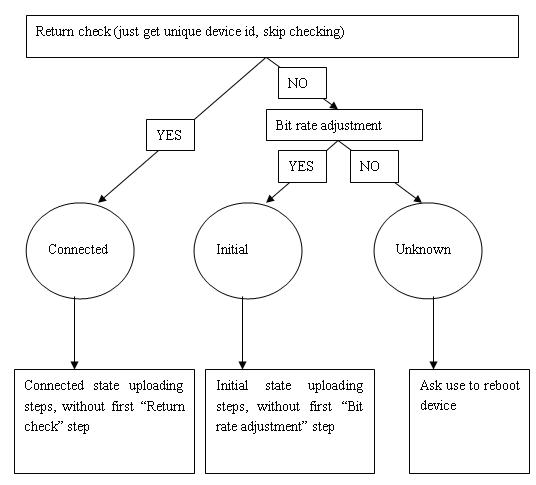
3.3 State checking
As the above descriptions, different state has different handling logic. So how to check the current state becomes important. The way used here is by help of “Return check” message inside which host can get device id if the device is connected. Here instead, host just get the id, skip checking it, if get the id successfully the device is in connected state; if failed the device is in initial state or unknown state, suppose it is in initial state, continue to use “bit rate adjustment” message, if succeed the device is in initial state, otherwise it is in unknown state.
Generally, as extensibility of Hitachi Software, the following graph is ok for all of the situations.