
SGPIO inverted clock qualifier
Hi,
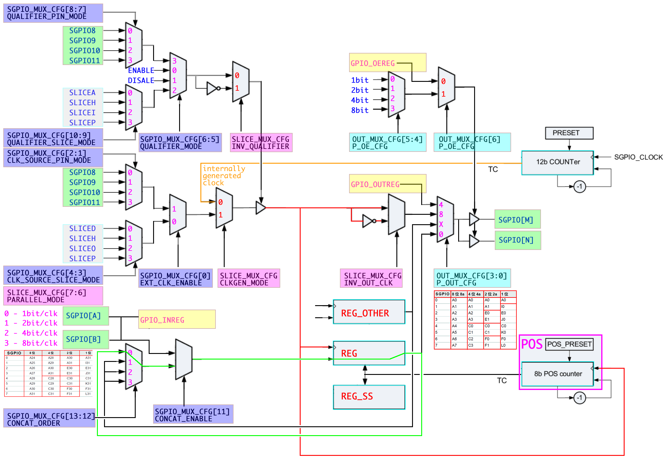
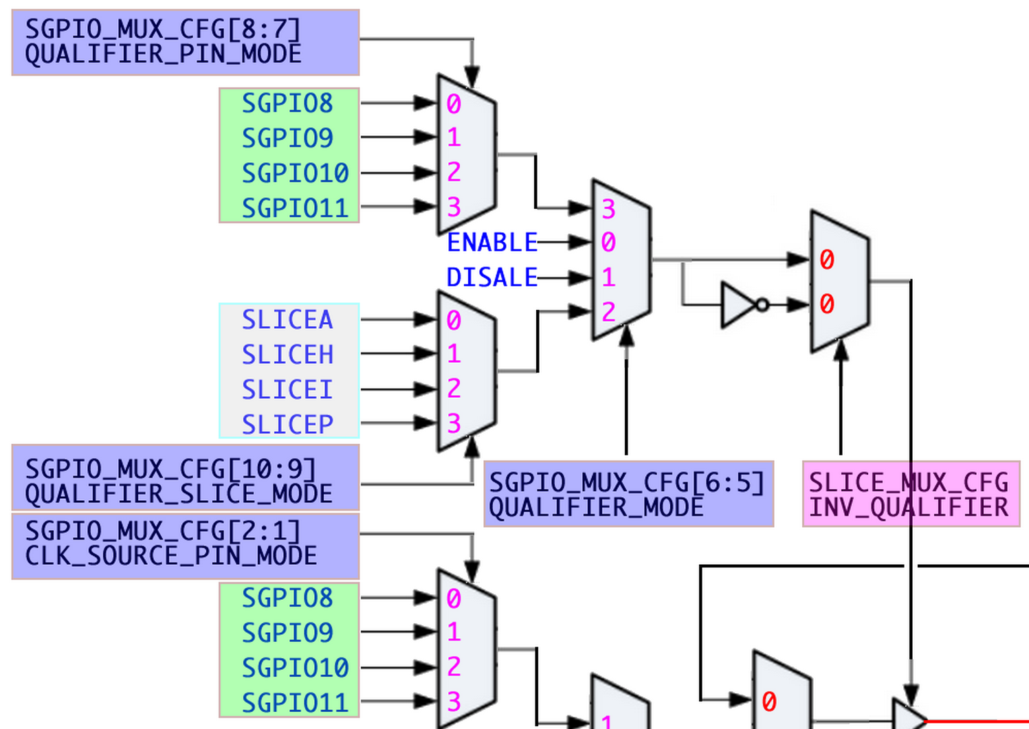
With bits 6:5 of SGPIO_MUX_CFG the QUALIFIER_MODE is selected (0x0=enable, 0x1=disable, 0x2=slice, 0x3=pin).
With bit 8 (INV_QUALIFIER) of SLICE_MUX_CFG one can invert the qualifier (0x0=normal qualifier, 0x1=inverted qualifier).
However if one sets INV_QUALIFIER=0x1, then the meanings of the first 2 alternatives of the QUALIFIER_MODE are reversed,
in other words: 0x0=disabled and 0x1=enabled.
I've tested this with a pin-qualifier using the LPC4330-Xplorer board.
Regards,
pdv

The observed behavior is indeed the case.
With bits 6:5 of SGPIO_MUX_CFG the QUALIFIER_MODE is selected (0x0=enable, 0x1=disable, 0x2=slice, 0x3=pin).
With bit 8 (INV_QUALIFIER) of SLICE_MUX_CFG one can invert the qualifier (0x0=normal qualifier, 0x1=inverted qualifier).
However if one sets INV_QUALIFIER=0x1, then the meanings of the first 2 alternatives of the QUALIFIER_MODE are reversed,
in other words: 0x0=disabled and 0x1=enabled.
Technically the qualifier_mode
- 0x0 makes the qualifier continues 1,
- 0x1 makes it continues 0,
- 0x2 ..
- 0x3 ..
The inversion turns the 1 into 0 and the 0 into 1 causing the strange observation.
regards,
NXP MCU Support