http://www.romanblack.com/smps/conv.htm
What is it?
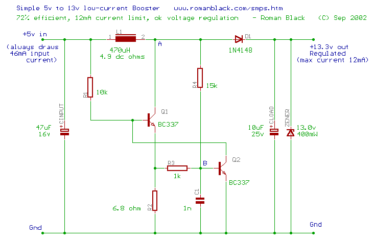
This is a simple smps voltage converter, it makes an output voltage of +13.3v from a "standard" +5v supply as used with logic chips.
I was contacted by hobby PIC programmer legend Myke Predko about designing a simple and cheap circuit to produce the 13v Vpp voltage needed to program PIC chips from a standard 5v regulated supply. This would eliminate the need for an smps 13v converter chip.
The circuit I settled on worked out very cheap, using a cheap 470uH "RF choke" type inductor and a very cheap 1N4148 small signal diode as the rectifier. The two transistor types are not critical. Measured efficiency was 72% which is quite reasonable from such a simple low power circuit.

The inductor can be a cheap small "RF choke" type.
Specs
- Tiny cheap RF type inductor
- Very cheap circuit (under 50 cents in parts!)
- Reliable self-starting
- 72% efficiency
- Input: 5v regulated
- Output: 13.3v @ 12mA maximum
The Circuit

How it works
The circuit regulates around peak inductor current, and since input voltage remains constant it also regulates input current and hence input power.
The regulation mechanism is R2, by ensuring that if R2 volts exceeds 0.6v main switch Q1 will turn off. The input current path is via L1, Q1 and R2.
Oscillation duty cycle is close to 50:50 so with an R2 of 6.8 ohms, peak inductor current is about 90mA and the average input current is about 46mA. Total current requirements can be reduced by increasing R2.
Notes
DO NOT run the circuit with no zener, and do not remove the zener when the circuit is running! Like any boost converter it may produce high voltages without the zener output clamp, and may damage transistors or the diode etc.
The circuit oscillates mainly based on inductor characteristics, and the cap C1 is not really a tuning cap, instead it provides some stability of oscillation waveform at a frequency determined mainly by inductance and the total load.
This booster is a CONSTANT POWER regulator. It always draws 46mA from the 5v supply (230mW), and delivers this power to the load at about 72% efficiency. So the load always gets about 13.3v and 12mA. If the output is overloaded at currents greater than 12mA the output voltage drops, providing a crude current regulation. If the output voltage is further overloaded to the point where it drops below 5v the diode starts passing current directly from the 5v supply and input current rises a LOT. Overloads like this should be avoided!
Important Notes!
The 13.3v output can be turned on or off by attaching the R1 resistor to +5v (as shown) or to 0v to turn it off. R1 can be attached to a PIC output pin to control the circuit.
When the circuit is OFF the output is about 4.3v and total current consumption is about 0.4mA.
When the circuit is ON the output is 13.3v and total current consumption is about 46mA.
For a PIC programmer application; the MCLR must rise very quickly to 13v to initiate programming. Use a 3k3 resistor in series with the output, going to the MCLR pin. Then use an additional NPN transistor to hold MCLR low as an open-collector pull-down. This transistor can then be switched and will switch the output voltage very quickly from 0v to 13v. (This is necessary with the smps 13v generator chips also.)
High Power / High Voltage?
Note! This circuit can be quite usable for higher power applications, and will oscillate reliably with a larger (high power) version of Q1 like a TO-220 darlington type. Remember it regulates INPUT current, and will provide a fairly regulated amount of power to the high voltage output load. It can be used as a simple 4 watt fluoro tube driver with a 12 volt input (for example). If you try this, try these values;
- Q1 = TIP122 darlington (see note)
- L1 = 470uH 500mA ferrite core inductor
- D1 = 1N4937 600v 1A fast rectifier
- R1 = 4k7
- R2 = 3.3 ohm
- R4 = 56k
- CLOAD = 0.1uF (not critical) but must be 630 volt type
With a 12v input this will run about 2 watts and make a usable light from the fluoro tube. Remove the zener and connect the output to a 4 watt (5 inch) fluoro tube like a F4T5 type. You may need a heatsink for Q1. I used a TIP-122 as it was lying around, but a high voltage darlington (>300v) is better. Remember this produces high voltages and you MUST always have the tube connected. Have fun and work safely with high voltages!
- end -