Standard Descriptors
-
A Device Descriptor describes general information about a USB device.
It includes information that applies globally to the device and
all of the device's configurations.
A USB device has only one device descriptor. -
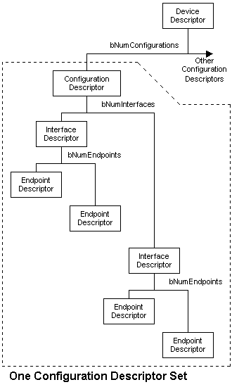
The Configuration Descriptor gives information about a specific device configuration.
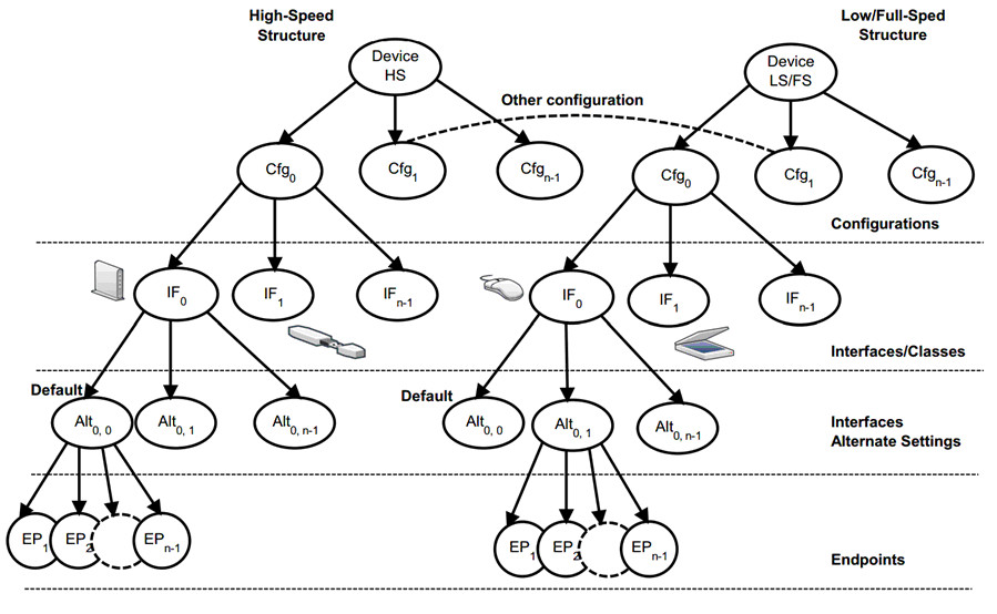
A USB device has one or more configuration descriptors.
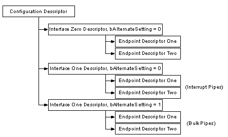
Each configuration has one or more interfaces and
each interface has zero or more endpoints. < N interfaces and N endpoints >
An endpoint is not shared among different interfaces within a single configuration,
although a single interface can have
several alternate settings which may use the same endpoint.
Endpoints may be shared among interfaces that are part
of different configurations without this restriction.
Configurations can only be activated by the standard control transfer set_configuration.
Different configurations can be used to change global device settings, such as power consumption. -
An Interface Descriptor describes a specific interface within a configuration.
A configuration provides one or more interfaces, each with zero or more endpoint descriptors
describing a unique set of endpoints within the configuration.
An interface may include alternate settings that allow the endpoints and/or their characteristics
to be varied after the device has been configured.
The default setting for an interface is always alternate setting zero.
Alternate settings can be selected exclusively by the standard control transfer set_interface.
For example a multifunctional device like a video camera with internal microphone
could have three alternate settings to change the bandwidth allocation on the bus.Camera activated Microphone activated Camera and microphone activated -
An Endpoint Descriptor contains information required by the host
to determine the bandwidth requirements of each endpoint.
An endpoint represents a logical data source or sink of a USB device.
The endpoint zero is used for all control transfers
and there is never a descriptor for this endpoint.
The USB specification uses the terms pipe and endpoint interchangably. -
String Descriptors are optional and provide additional information
in human readable unicode format.
They can be used for vendor and device names or serial numbers. -
USB Interface Association Descriptor (IAD)
IAD是Interface Association Descriptor,功能是把多个接口定义为一个类设备。
Windows下,IAD和Composite设备在设备管理器中没有什么区别,甚至使用的驱动也都是Composite驱动
USB interface association descriptor allows the device
to group interfaces that belong to a function.
The Universal Serial Bus Specification, revision 2.0,
does not support grouping more than one interface of a composite device
within a single function.
However, the USB Device Working Group (DWG) created USB device classes
that allow for functions with multiple interfaces, and the USB Implementor's Forum
issued an Engineering Change Notification (ECN)
that defines a mechanism for grouping interfaces.
The ECN specifies a USB descriptor, called the Interface Association Descriptor (IAD),
that allows hardware manufacturers to define groupings of interfaces.
The device classes that are most likely to use IADs include:
USB Video Class Specification (Class Code - 0x0E)
USB Audio Class Specification (Class Code - 0x01)
USB Bluetooth Class Specification (Class Code - 0xE0)
Windows 7, Windows Server 2008, Windows Vista, Microsoft Windows Server 2003 Service Pack 1 (SP1),
and Microsoft Windows XP Service Pack 2 (SP2) support IADs.
Manufacturers of composite devices typically assign a value of zero ( 0x00 )
in the device descriptor, as specified by the Universal Serial Bus Specification.
bDeviceClass      0x00 - defined at Interface level
bDeviceSubClass    0x00 - Unknown
bDeviceProtocol    0x00 - Unknown
This allows the manufacturer to associate
each individual interface with a different device class and protocol.
The USB-IF core team has devised a special class and protocol code set
that notifies the operating system that one or more IADs are present in device firmware.
A device's device descriptor must have the values that appear in the following table
or else the operating system will not detect
the device's IADs or group the device's interfaces properly.
These code values also alert versions of Windows that do not support IADs
to install a special-purpose bus driver that correctly enumerates the device.
Without these codes in the device descriptor, the system might fail to enumerate the device,
or the device might not work properly.
bDeviceClass      0xEF
bDeviceSubClass    0x02
bDeviceProtocol    0x01
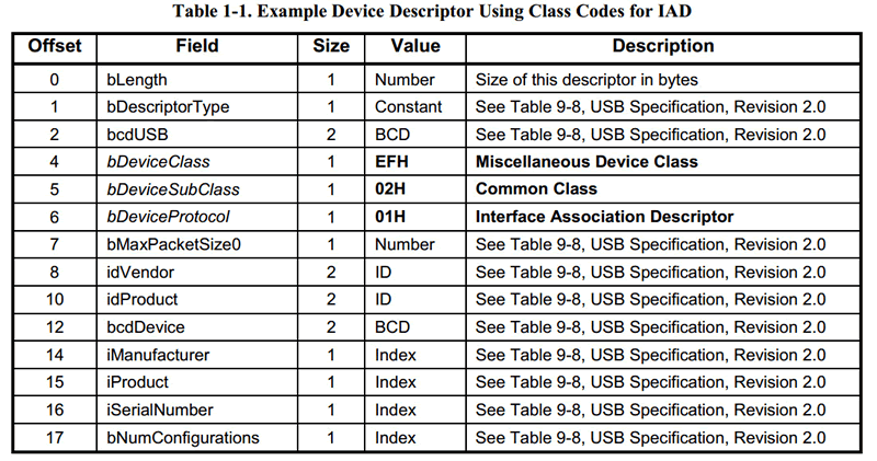
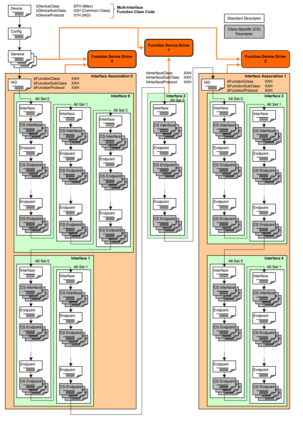
A device can have more than one IAD. Each IAD must be located immediately
before the interfaces in the interface group that the IAD describes.
The function class (bFunctionClass), subclass (bFunctionSubclassClass),
and protocol (bFunctionProtocol) fields of the IAD must contain the values
that are specified by the USB device class that describes the interfaces in the function.
The class and subclass fields of the IAD are not required to
match the class and subclass fields of the interfaces
in the interface collection that the IAD describes.
However, Microsoft recommends that the first interface of the collection
have class and subclass fields that match the class and subclass fields of the IAD.
The following table indicates which fields should match.
IAD field           Corresponding interface field
bFunctionClass         bInterfaceClass
bFunctionSubclassClass  bInterfaceSubClass
The bFirstInterface field of the IAD indicates the number of the first interface in the function.
The bInterfaceCount field of the IAD indicates how many interfaces are in the interface collection.
Interfaces in an IAD interface collection must be contiguous
(there can be no gaps in the list of interface numbers),
and so a count with a first interface number is sufficient
to specify all of the interfaces in the collection. < First First+1 .. Frist+Count-1 >
USB Interface Association Descriptor Example
The following illustrates a descriptor layout for a composite USB device.
The example device has two functions:
Function 1: Video Class
This function is defined by an interface association descriptor (IAD)
and contains two interfaces: interface zero (0) and interface one (1).
The system generates hardware and compatible identifiers (IDs) for the function,
as described in Enumeration of Interface Collections on USB Devices with IADs.
After matching the appropriate INF file, the system loads the Video Class driver stack.
Function 2: Human Input Device
This function contains only one interface: interface two (2).
The system generates hardware and compatible IDs for the function,
as described in Enumeration of Interfaces on USB Composite Devices.
After matching the appropriate INF file, the system loads the Human Input Device (HID) class driver.
--------------------------------------------------------------------------------
Device Descriptor:
--------------------------------------------------------------------------------
BYTE  bLength             0x12
BYTE  bDescriptorType     0x01
WORD  bcdUSB              0x0200
BYTE  bDeviceClass        0xEF
BYTE  bDeviceSubClass     0x02
BYTE  bDeviceProtocol     0x01
BYTE  bMaxPacketSize0     0x40
WORD  idVendor            0x045E
WORD  idProduct           0xFFFF
WORD  bcdDevice           0x0100
BYTE  iManufacturer       0x01
WORD  iProduct            0x02
WORD  iSerialNumber       0x03
BYTE  bNumConfigurations  0x01

--------------------------------------------------------------------------------
Configuration Descriptor:
--------------------------------------------------------------------------------
BYTE  bLength             0x09
BYTE  bDescriptorType     0x02
WORD  wTotalLength        0x....
BYTE  bNumInterfaces      0x03    < Interface 0, 1, 2 >
BYTE  bConfigurationValue 0x01
BYTE  iConfiguration      0x01
BYTE  bmAttributes        0x80 (BUS Powered)
BYTE  bMaxPower           0xFA (500 mA)

--------------------------------------------------------------------------------
Interface Association Descriptor:
--------------------------------------------------------------------------------
BYTE  bLength             0x08
BYTE  bDescriptorType     0x0B
BYTE  bFirstInterface     0x00    < Interface 0 >
BYTE  bInterfaceCount     0x02    < Interface 1 >
BYTE  bFunctionClass      0x0E
BYTE  bFunctionSubClass   0x03
BYTE  bFunctionProtocol   0x00
BYTE  iFunction           0x04

--------------------------------------------------------------------------------
Interface Descriptor (Video Control):
--------------------------------------------------------------------------------
BYTE  bLength             0x09
BYTE  bDescriptorType     0x04
BYTE  bInterfaceNumber    0x00    < Interface 0 >
BYTE  bAlternateSetting   0x00
BYTE  bNumEndpoints       0x01
BYTE  bInterfaceClass     0x0E
BYTE  bInterfaceSubClass  0x01
BYTE  bInterfaceProtocol  0x00
BYTE  iInterface          0x05

Class Specific Descriptor(s):
Endpoint Descriptor(s):

--------------------------------------------------------------------------------
Interface Descriptor (Video Streaming):
--------------------------------------------------------------------------------
BYTE  bLength             0x09
BYTE  bDescriptorType     0x04
BYTE  bInterfaceNumber    0x01    < Interface 1 >
BYTE  bAlternateSetting   0x00
BYTE  bNumEndpoints       0x01
BYTE  bInterfaceClass     0x0E
BYTE  bInterfaceSubClass  0x02
BYTE  bInterfaceProtocol  0x00
BYTE  iInterface          0x06

Class Specific Descriptor(s):
Endpoint Descriptor(s):

--------------------------------------------------------------------------------
Interface Descriptor (Human Input Devices):
--------------------------------------------------------------------------------
BYTE  bLength             0x09
BYTE  bDescriptorType     0x04
BYTE  bInterfaceNumber    0x02    < Interface 2 >
BYTE  bAlternateSetting   0x00
BYTE  bNumEndpoints       0x01
BYTE  bInterfaceClass     0x03
BYTE  bInterfaceSubClass  0x01
BYTE  bInterfaceProtocol  0x01
BYTE  iInterface          0x07

Class Specific Descriptor(s):
Endpoint Descriptor(s):
http://docs.oracle.com/cd/E19082-01/819-3196/usb-10/index.html
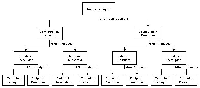
A descriptor tree for a device with two configurations
might look like the tree shown in the following figure.

The dev_cfg array shown in the above figure contains nodes that correspond to configurations.
Each node contains the following information:
-
A parsed configuration descriptor
-
A pointer to an array of descriptors that correspond to the interfaces of that configuration
-
A pointer to an array of class-specific or vendor-specific raw data, if any exists
The node that represents the second interface of the second indexed configuration
is atdev_cfg[1].cfg_if[1] in the diagram.
That node contains an array of nodes that represent the alternate settings for that interface.
The hierarchy of USB descriptors propagates through the tree.
ASCII strings from string descriptor data are attached
where the USB specification says these strings exist.
The array of configurations is non-sparse and is indexed by the configuration index.
The first valid configuration (configuration 1) is dev_cfg[0].
Interfaces and alternate settings have indices that align with their numbers.
Endpoints of each alternate setting are indexed consecutively.
The first endpoint of each alternate setting is at index 0.
This numbering scheme makes the tree easy to traverse.
For example, the raw descriptor data of
endpoint index 0, alternate 0, interface 1, configuration index 1
is at the node defined by the following path:
dev_cfg[1].cfg_if[1].if_alt[0].altif_ep[0].ep_descr
An alternative to using the descriptor tree directly is
using the usb_lookup_ep_data(9F) function.
The usb_lookup_ep_data(9F) function takes as arguments
the interface, alternate, which endpoint, endpoint type, and direction.
You can use the usb_lookup_ep_data(9F) function
to traverse the descriptor tree to get a particular endpoint.
See the usb_get_dev_data(9F) man page for more information.
http://www.beyondlogic.org/usbnutshell/usb5.shtml
