- 中文名
- 脉冲编码调制
- 外文名
- Pulse Code Modulation
- 简 称
- PCM
- 发现者
- A.里弗斯
- 发现时间
- 1937年
- 用 于
- 市话中继传输等
PCM(脉冲编码调制)_百度百科 https://baike.baidu.com/item/PCM/1568054

Pulse-code modulation - Wikipedia https://en.wikipedia.org/wiki/Pulse-code_modulation

Modulation
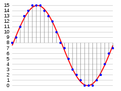
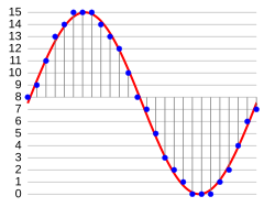
In the diagram, a sine wave (red curve) is sampled and quantized for PCM. The sine wave is sampled at regular intervals, shown as vertical lines. For each sample, one of the available values (on the y-axis) is chosen by some algorithm. This produces a fully discrete representation of the input signal (blue points) that can be easily encoded as digital data for storage or manipulation. For the sine wave example at right, we can verify that the quantized values at the sampling moments are 8, 9, 11, 13, 14, 15, 15, 15, 14, etc. Encoding these values as binary numbers would result in the following set of nibbles: 1000 (= 23×1+22×0+21×0+20×0 = 8+0+0+0 = 8), 1001, 1011, 1101, 1110, 1111, 1111, 1111, 1110, etc. These digital values could then be further processed or analyzed by a digital signal processor. Several PCM streams could also be multiplexed into a larger aggregate data stream, generally for transmission of multiple streams over a single physical link. One technique is called time-division multiplexing (TDM) and is widely used, notably in the modern public telephone system.
The PCM process is commonly implemented on a single integrated circuit generally referred to as an analog-to-digital converter (ADC).
