标准库中有很多模块。我们就一个模块一个模块的分析。慢慢看懂就可以了。
其实看几个就会明白。基本上的套路都是一样的。
RCC模块、时钟
stm32f10x_rcc.c
stm32f10x_rcc.h
我们都知道在单片机中,时钟是不可缺少的。
分析RCC之前我们先简单的说下如何通过起始文件调用时钟的,复制代码:
Reset_Handler PROC
EXPORT Reset_Handler [WEAK]
IMPORT __main
IMPORT SystemInit
LDR R0, =SystemInit
BLX R0
LDR R0, = __main
BX R0
ENDP
这是启始文件中的一段代码,会汇编语言编写:大概就是,Reset_Handler PROC 复位中断 程序
这是一个复位中断,复位中断之后,分别import导入 __main,SystemInit,跳入SystemInit,__main...启始文件就是这样跳入C的世界的。
但是在跳入C之前有LDR R0, =SystemInit 先进入了SystemInit,我们通过查找可以知道。在文件System_stm32f10x.c中,void SystemInit (void){.....}函数
这个函数是通过之前创建工程时的宏定义STM32F10X_HD判断,最后会用的是72M时钟。配置完时钟之后,在调入main中,所以说要是对时钟没有特殊要求,就不用更改时钟,就用默认的72M就可以了。
时钟模块中其实讲了很多东西。我们就慢慢分析下吧。
stm32f10x_rcc.c文件
我们打开stm32f10x_rcc.c文件首先看到的是
/* -------------------------------------------------------------------- RCC registers bit address in the alias region -------------------------------------------------------------- */
#define RCC_OFFSET (RCC_BASE - PERIPH_BASE) //bitband, RCC registers 位段基地址
/* ---------- CR Register ----------*/ //配置CR寄存器
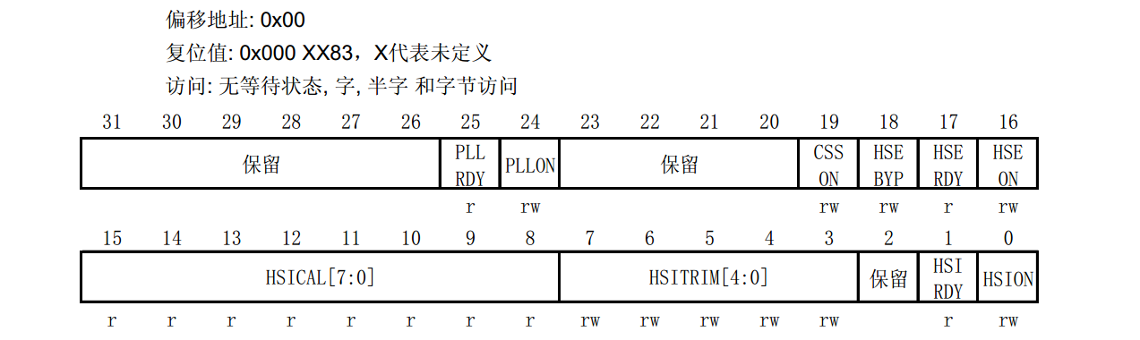
/* Alias word address of HSION bit */ //HSION位
#define CR_OFFSET (RCC_OFFSET + 0x00) //RCC中的CR寄存器的位段地址
#define HSION_BitNumber 0x00 //HSION在CR寄存器中的0位
#define CR_HSION_BB (PERIPH_BB_BASE + (CR_OFFSET * 32) + (HSION_BitNumber * 4)) //根据公式对应出BB(bitband)地址
/* Alias word address of PLLON bit */
#define PLLON_BitNumber 0x18 //0x18 PLLON在寄存器中的24位
#define CR_PLLON_BB (PERIPH_BB_BASE + (CR_OFFSET * 32) + (PLLON_BitNumber * 4))
#ifdef STM32F10X_CL //这个是CL的芯片.....如果定义了STM32F10X_CL
/* Alias word address of PLL2ON bit */
#define PLL2ON_BitNumber 0x1A
#define CR_PLL2ON_BB (PERIPH_BB_BASE + (CR_OFFSET * 32) + (PLL2ON_BitNumber * 4))
/* Alias word address of PLL3ON bit */
#define PLL3ON_BitNumber 0x1C
#define CR_PLL3ON_BB (PERIPH_BB_BASE + (CR_OFFSET * 32) + (PLL3ON_BitNumber * 4))
#endif /* STM32F10X_CL */
/* Alias word address of CSSON bit */
#define CSSON_BitNumber 0x13
#define CR_CSSON_BB (PERIPH_BB_BASE + (CR_OFFSET * 32) + (CSSON_BitNumber * 4))
/* --- CFGR Register ---*/ //RCC中的CFGR寄存器
/* Alias word address of USBPRE bit */
#define CFGR_OFFSET (RCC_OFFSET + 0x04) //RCC中的CR寄存器的位段地址 ----基地址加上偏移量
#ifndef STM32F10X_CL //如果没有预定义STM32F10X_CL
#define USBPRE_BitNumber 0x16
#define CFGR_USBPRE_BB (PERIPH_BB_BASE + (CFGR_OFFSET * 32) + (USBPRE_BitNumber * 4))
#else
#define OTGFSPRE_BitNumber 0x16
#define CFGR_OTGFSPRE_BB (PERIPH_BB_BASE + (CFGR_OFFSET * 32) + (OTGFSPRE_BitNumber * 4))
#endif /* STM32F10X_CL */
一直到200多行一直都是按这样的方法进行预定义,查手册就可以看出,固件库把一个可用的位,先按名字预定义了,为了用户方便使用。
在.C文件中宏定义,一般都是在这个.C文件中使用的。在.h中的宏定义,是为了方便外部调用的。
接下来就是函数了
/**
* @brief Resets the RCC clock configuration to the default reset state.
* @param None
* @retval None
*/
void RCC_DeInit(void){} //恢复默认配置状态
/**
* @brief Configures the External High Speed oscillator (HSE).
* @note HSE can not be stopped if it is used directly or through the PLL as system clock.
* @param RCC_HSE: specifies the new state of the HSE.
* This parameter can be one of the following values:
* @arg RCC_HSE_OFF: HSE oscillator OFF
* @arg RCC_HSE_ON: HSE oscillator ON
* @arg RCC_HSE_Bypass: HSE oscillator bypassed with external clock
* @retval None
*/
void RCC_HSEConfig(uint32_t RCC_HSE){} //配置HSE
/**
* @brief Waits for HSE start-up.
* @param None
* @retval An ErrorStatus enumuration value:
* - SUCCESS: HSE oscillator is stable and ready to use
* - ERROR: HSE oscillator not yet ready
*/
ErrorStatus RCC_WaitForHSEStartUp(void){} //等待HSE启动,外部高速时钟 ,可以返回是否成功ErrorStatus,一个枚举类型
有很多函数
打开外设时钟,函数
/**
* @brief Enables or disables the High Speed APB (APB2) peripheral clock.
* @param RCC_APB2Periph: specifies the APB2 peripheral to gates its clock.
* This parameter can be any combination of the following values:
* @arg RCC_APB2Periph_AFIO, RCC_APB2Periph_GPIOA, RCC_APB2Periph_GPIOB,
* RCC_APB2Periph_GPIOC, RCC_APB2Periph_GPIOD, RCC_APB2Periph_GPIOE,
* RCC_APB2Periph_GPIOF, RCC_APB2Periph_GPIOG, RCC_APB2Periph_ADC1,
* RCC_APB2Periph_ADC2, RCC_APB2Periph_TIM1, RCC_APB2Periph_SPI1,
* RCC_APB2Periph_TIM8, RCC_APB2Periph_USART1, RCC_APB2Periph_ADC3,
* RCC_APB2Periph_TIM15, RCC_APB2Periph_TIM16, RCC_APB2Periph_TIM17,
* RCC_APB2Periph_TIM9, RCC_APB2Periph_TIM10, RCC_APB2Periph_TIM11
* @param NewState: new state of the specified peripheral clock.
* This parameter can be: ENABLE or DISABLE.
* @retval None
*/
void RCC_APB2PeriphClockCmd(uint32_t RCC_APB2Periph, FunctionalState NewState){} //使能APB2
/**
* @brief Enables or disables the Low Speed APB (APB1) peripheral clock.
* @param RCC_APB1Periph: specifies the APB1 peripheral to gates its clock.
* This parameter can be any combination of the following values:
* @arg RCC_APB1Periph_TIM2, RCC_APB1Periph_TIM3, RCC_APB1Periph_TIM4,
* RCC_APB1Periph_TIM5, RCC_APB1Periph_TIM6, RCC_APB1Periph_TIM7,
* RCC_APB1Periph_WWDG, RCC_APB1Periph_SPI2, RCC_APB1Periph_SPI3,
* RCC_APB1Periph_USART2, RCC_APB1Periph_USART3, RCC_APB1Periph_USART4,
* RCC_APB1Periph_USART5, RCC_APB1Periph_I2C1, RCC_APB1Periph_I2C2,
* RCC_APB1Periph_USB, RCC_APB1Periph_CAN1, RCC_APB1Periph_BKP,
* RCC_APB1Periph_PWR, RCC_APB1Periph_DAC, RCC_APB1Periph_CEC,
* RCC_APB1Periph_TIM12, RCC_APB1Periph_TIM13, RCC_APB1Periph_TIM14
* @param NewState: new state of the specified peripheral clock.
* This parameter can be: ENABLE or DISABLE.
* @retval None
*/
void RCC_APB1PeriphClockCmd(uint32_t RCC_APB1Periph, FunctionalState NewState){}
RCC启动时钟,系统时钟里已经帮我们配置好了。
我们实际应用中,打开外设库,修改时钟就可以了。
需要时查看函数声明。