1 Scope of Document
This document describes am335x cpufreq technology insider.
2 Requiremen
2.1 Function Requirement
How to get current cpufreq, and to change cpufreq. Learning Processor Clocking Control(PPC) Interface Specification, learning APCI Specification.
2.2 Performance Requirement
NA
3 Functional Description
3.1 Functional Block Diagram
Am335x cpufreq be set by inner contex-M3,The inner contex-M3 running platform firmware. The platform firmware can be load , when booting kernel.
[ 2.118896] Power Management for AM33XX family
[ 2.127075] Trying to load am335x-pm-firmware.bin (60 secs timeout)
[ 2.137084] Copied the M3 firmware to UMEM
3.2 PCC interface specification
3.2.1 Overview
The Processor Clocking Control (PCC) interface is implemented by platform firmware in
order to provide a channel for the Operating System to direct and
obtain performance
information on a per-processor basis in cases where the platform
firmware would
normally be directing the control of the processor performance. In
this model the
platform firmware remains in direct control of the processor
clocking control registers.
The Operating System computes the required performance for each
processor and
communicates this to the platform firmware via the PCC shared
memory interface. The
platform firmware is responsible for managing the hardware
clocking controls in order to
deliver the requested performance. The interface also provides the
capability for the
Operating System to obtain the actual performance level delivered.
In cases where the
platform is unable to meet the Operating System request, such as a
thermal or power
budget conditions, flags are set to indicate this to the Operating
System
The Processor Clocking Control
interface relies on a reserved area in the system memory
map for communications between the platform firmware and the
Operating System.
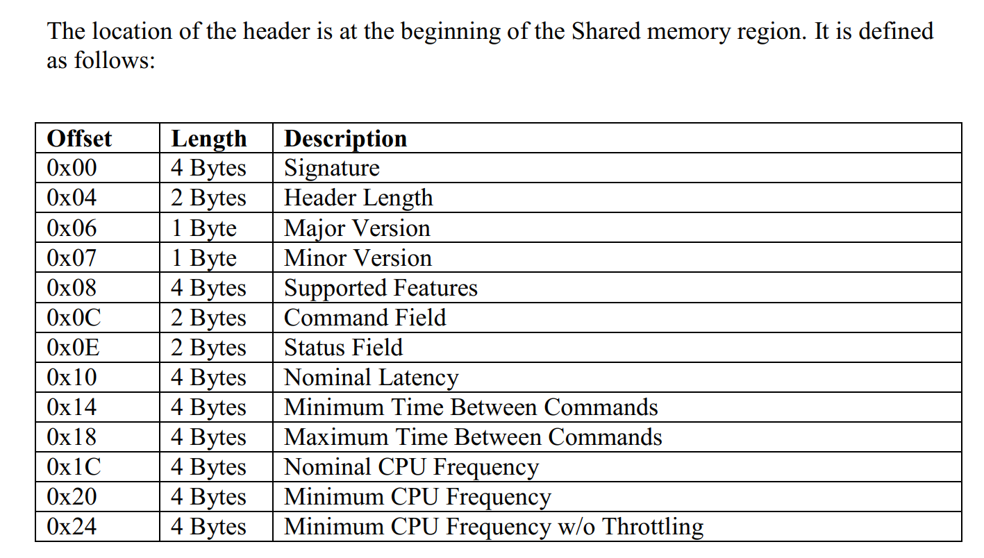
The shared memory region is a single header structure in memory. The region of
Memory is specified in she SharedMemoryRegion field obtained ty evaluating the PCCH() method. The region contains a haeder followed by one input and ome output buffer for each logical processor.
3.2.2 PCC interface header info
3.2.3 PCC interface commad and alert mechanism.
Support command :
- Get Average Frequency
- Set Desired Frequency
Alert Mechanism:
- Operationg System to Platform Doorbell.
- Platform to Operating System Doorbell.
4 Porting
4.1 Kernel porting
NA
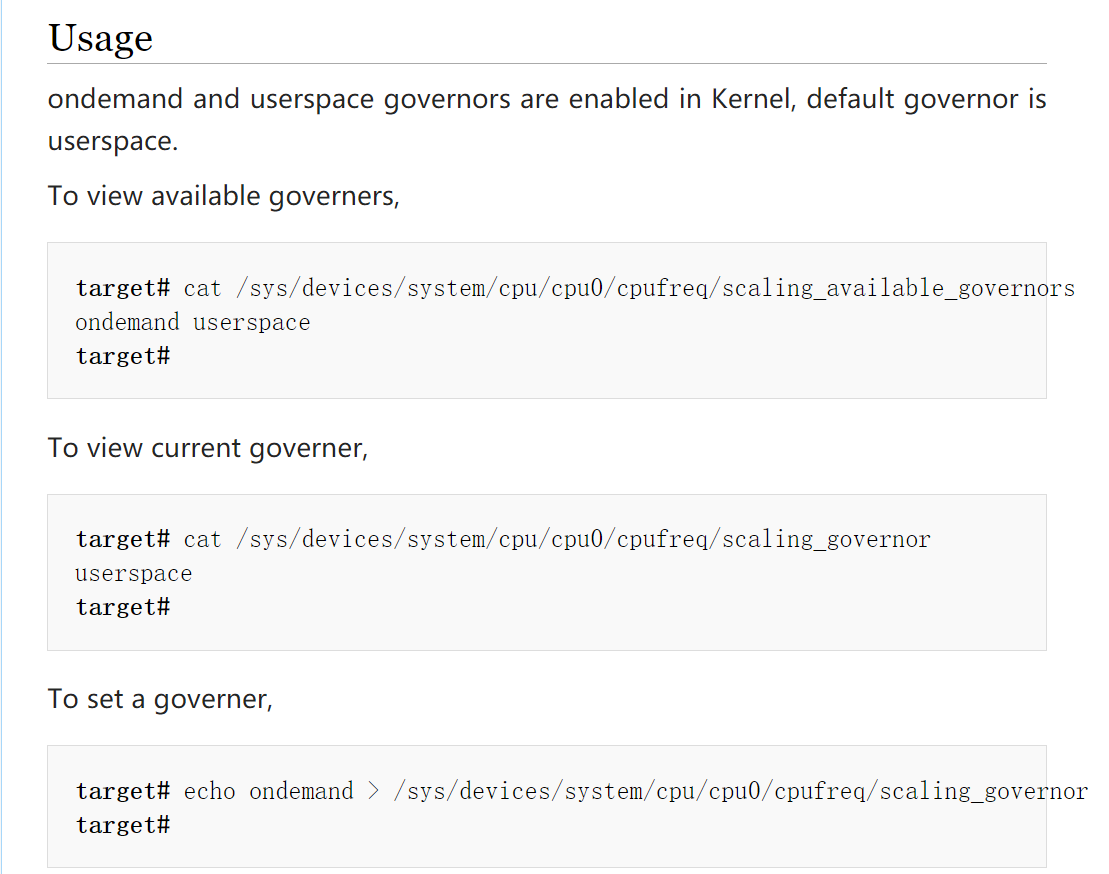
4.2 Application Interface
Set cpufreq mode: