锁相环PLL默认输入前端有个IBUFG单元,在输出端有个BUFG单元,而两个BUFG(IBUFG)不能相连,所以会报这样的错:
ERROR:NgdBuild:770 - IBUFG 'u_pll0/clkin1_buf' and BUFG 'BUFG_inst' on net
'clkin_w' are lined up in series. Buffers of the same direction cannot be
placed in series.
ERROR:NgdBuild:924 - input pad net 'clkin_w' is driving non-buffer primitives:
如下示例代码:
[Demo1]
 1 // demo1 two bufg connect
 2
 3 module iobuf(
 4
 5    input   clk,
 6
 7    input   rst,
 8
 9    output  led
10
11    );
12
13  wire clkin_w;
14
15  BUFG BUFG_inst(
16
17       .O(clkin_w),           // Clock buffer output
18
19       .I(clk)                   // Clock buffer input
20
21      );
22
23  pll0 u_pll0(
24
25       .CLK_IN1(clkin_w),      // IN
26
27       .CLK_OUT1(clkout),  // OUT
28
29       .RESET(rst));       // IN
30
31 assign led = clkout;
32
33 endmodule
普通IO不能直接做锁相环的输入,所以会报这样的错:
ERROR:Place:1397 - A clock IOB / MMCM clock component pair have been found that
are not placed at an optimal clock IOB / MMCM site pair. The clock IOB
component <clk> is placed at site <A18>. The corresponding MMCM component
<u_pll0/mmcm_adv_inst> is placed at site <MMCME2_ADV_X0Y0>. The clock IO can
use the fast path between the IOB and the MMCM if the IOB is placed on a
Clock Capable IOB site that has dedicated fast path to MMCM sites within the
same clock region. You may want to analyze why this problem exists and
correct it. If this sub optimal condition is acceptable for this design, you
may use the CLOCK_DEDICATED_ROUTE constraint in the .ucf file to demote this
message to a WARNING and allow your design to continue. However, the use of
this override is highly discouraged as it may lead to very poor timing
results. It is recommended that this error condition be corrected in the
design. A list of all the COMP.PINs used in this clock placement rule is
ERROR:Pack:1654 - The timing-driven placement phase encountered an error.
如果有ucf中加上这句约束:
1 NET clk CLOCK_DEDICATED_ROUTE = FALSE;
依旧会报错,在ZYNQ7000系列,这样还是通不过,如下:
ERROR:PhysDesignRules:2256 - Unsupported MMCME2_ADV configuration. The signal
u_pll0/clkin1 on the CLKIN1 pin of MMCME2_ADV comp u_pll0/mmcm_adv_inst with
COMPENSATION mode ZHOLD must be driven by a clock capable IOB.
ERROR:Pack:1642 - Errors in physical DRC.
如下示例代码
[Demo2]
 1 // demo2 regular io directly connect to PLL
 2
 3 module iobuf(
 4
 5     input clk,
 6
 7    input     rst,
 8
 9    output   led
10
11  );
12
13
14
15  pll0 u_pll0(
16
17     .CLK_IN1(clk),      // IN
18
19     .CLK_OUT1(clkout),  // OUT
20
21     .RESET(rst));       // IN
22
23 assign led = clkout;
24
25 endmodule
使用普通的IO,再连接bufg来连到时钟线上,
仍会报这样的错误,因为还是两bufg相连了:
ERROR:NgdBuild:770 - IBUFG 'u_pll0/clkin1_buf' and BUFG 'BUFG_inst' on net
'clkin_w' are lined up in series. Buffers of the same direction cannot be
placed in series.
ERROR:NgdBuild:924 - input pad net 'clkin_w' is driving non-buffer primitives:
修改为如下:
[Demo3]
 1 // dem3 regular io with BUFG then connect to PLL which with"No Buffer" setting
 2
 3  module iobuf(
 4
 5    input  clk,
 6
 7    input  rst,
 8
 9    output  led
10
11    );
12
13  wire clkin_w;
14
15  BUFG BUFG_inst (
16
17       .O(clkin_w),           // Clock buffer output
18
19       .I(clk)                   // Clock buffer input
20
21    );
22
23  pll0 u_pll0(
24
25     .CLK_IN1(clkin_w),      // IN
26
27     .CLK_OUT1(clkout),  // OUT
28
29     .RESET(rst));       // IN
30
31 assign led = clkout;
32
33 endmodule
PLL的设置如下图,
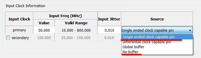
这样普通IO就可以当作PLL的时钟输入了,顺利产生bit;
时钟还是最好用全局时钟IO,画图时一定要注意:)
zc702里没有global clock的概念了,但有了很多专用时钟脚,用起来一样;
[结论]
不能将两个PLL进行串联
普通IO不能直接作PLL的时钟输入,专用时钟管脚可以;
普通IO可以通过BUFG再连到PLL的时钟输入上,但要修改PLL的设置 input clk的选项中要选择"No Buffer";
具体内部布局分配可以通过 Xilinx的FPGA Editor来查看,
ZYNQ的时钟管理也和之前的片子略有不同,之后在另一篇介绍,相关文档 <ug472_7Series_Clocking.pdf>