听别人推荐了一个Verilog刷题网站:https://hdlbits.01xz.net/wiki/Main_Page
01.Build a circuit with no inputs and one output. That output should always drive 1 (or logic high).
module top_module( output one );

// Insert your code here
    assign one = 1'b1;

endmodule
02.Build a circuit with no inputs and one output that outputs a constant 0.
module top_module(output zero);
// Module body starts after semicolon
    assign zero = 1'b0;
endmodule
03.Create a module with one input and one output that behaves like a wire.["continuous assignment" (assign left_side = right_side;)]
module top_module( input in, output out );
    assign out = in;
endmodule
04.Create a module with 3 inputs and 4 outputs that behaves like wires that makes these connections:
a -> w
b -> x
b -> y
c -> z
module top_module(
    input a,b,c,
    output w,x,y,z );
    assign w=a;
    assign x=b;
    assign y=b;
    assign z=c;
endmodule
        // If we're certain about the width of each signal, using
    // the concatenation operator is equivalent and shorter:
    // assign {w,x,y,z} = {a,b,b,c};
05.Create a module that implements a NOT gate.
module top_module( input in, output out );
    not not1(out,in);
endmodule
//答案:
module top_module( input in, output out );
    assign out = ~in;
endmodule
06.Create a module that implements an AND gate.
module top_module(
    input a,
    input b,
    output out );
    assign out=a&&b;
endmodule
07.Create a module that implements a NOR gate. A NOR gate is an OR gate with its output inverted. A NOR function needs two operators when written in Verilog.
module top_module(
    input a,
    input b,
    output out );
    assign out=~(a||b);
endmodule
08.Create a module that implements an XNOR gate.
module top_module(
    input a,
    input b,
    output out );
    assign out=~(((~a)||(~b))&&(a||b));
endmodule
09.Implement the following circuit.
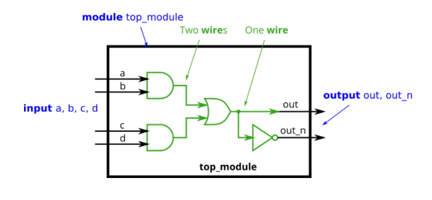
module top_module (
    input a,
    input b,
    input c,
    input d,
    output out,
    output out_n );

    wire w1, w2;        // Declare two wires (named w1 and w2)
    assign w1 = a&b;    // First AND gate
    assign w2 = c&d;    // Second AND gate
    assign out = w1|w2;    // OR gate: Feeds both 'out' and the NOT gate

    assign out_n = ~out;    // NOT gate

endmodule
10.Create a module with the same functionality as the 7458 chip. It has 10 inputs and 2 outputs. You may choose to use an assign statement to drive each of the output wires, or you may choose to declare (four) wires for use as intermediate signals, where each internal wire is driven by the output of one of the AND gates. For extra practice, try it both ways.
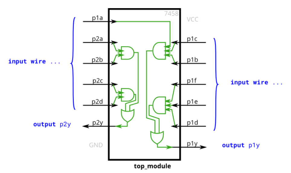
module top_module (
    input p1a, p1b, p1c, p1d, p1e, p1f,
    output p1y,
    input p2a, p2b, p2c, p2d,
    output p2y );
    wire p11,p12,p21,p22;
    assign p11=p1a&&p1b&&p1c;
    assign p12=p1d&&p1e&&p1f;
    assign p21=p2a&&p2b;
    assign p22=p2d&&p2c;
    assign p1y=p11||p12;
    assign p2y=p21||p22;
endmodule
11.Build a circuit that has one 3-bit input, then outputs the same vector, and also splits it into three separate 1-bit outputs. Connect output o0 to the input vector's position 0, o1 to position 1, etc.
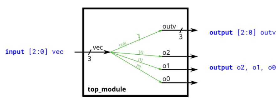
module top_module (
    input wire [2:0] vec,
    output wire [2:0] outv,
    output wire o2,
    output wire o1,
    output wire o0  ); // Module body starts after module declaration
    assign outv=vec;
    assign o0=vec[0];
    assign o1=vec[1];
    assign o2=vec[2];
endmodule
// This is ok too: assign {o2, o1, o0} = vec
12.Build a combinational circuit that splits an input half-word (16 bits, [15:0] ) into lower [7:0] and upper [15:8] bytes.
module top_module (
    input [15:0] in,
    output [7:0] out_hi,
    output [7:0] out_lo
);

    assign out_hi = in[15:8];
    assign out_lo = in[7:0];

    // Concatenation operator also works: assign {out_hi, out_lo} = in;

endmodule
13.A 32-bit vector can be viewed as containing 4 bytes (bits [31:24], [23:16], etc.). Build a circuit that will reverse the byte ordering of the 4-byte word.
AaaaaaaaBbbbbbbbCcccccccDddddddd => DdddddddCcccccccBbbbbbbbAaaaaaaa
module top_module (
    input [31:0] in,
    output [31:0] out
);

    assign out[31:24] = in[ 7: 0];
    assign out[23:16] = in[15: 8];
    assign out[15: 8] = in[23:16];
    assign out[ 7: 0] = in[31:24];

endmodule
14.Build a circuit that has two 3-bit inputs that computes the bitwise-OR of the two vectors, the logical-OR of the two vectors, and the inverse (NOT) of both vectors. Place the inverse of b in the upper half of out_not (i.e., bits [5:3]), and the inverse of a in the lower half.
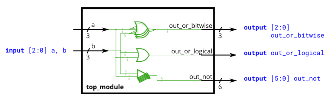
module top_module(
    input [2:0] a,
    input [2:0] b,
    output [2:0] out_or_bitwise,
    output out_or_logical,
    output [5:0] out_not
);
    assign out_or_bitwise[0]=a[0]||b[0];
    assign out_or_bitwise[1]=a[1]||b[1];
    assign out_or_bitwise[2]=a[2]||b[2];
    assign out_or_logical=a||b;
    assign out_not[0]=~a[0];
    assign out_not[1]=~a[1];
    assign out_not[2]=~a[2];
    assign out_not[3]=~b[0];
    assign out_not[4]=~b[1];
    assign out_not[5]=~b[2];
endmodule
//以上是不好好看书直接撸题的下场,答案:
module top_module(
    input [2:0] a,
    input [2:0] b,
    output [2:0] out_or_bitwise,
    output out_or_logical,
    output [5:0] out_not
);

    assign out_or_bitwise = a | b;
    assign out_or_logical = a || b;

    assign out_not[2:0] = ~a;    // Part-select on left side is o.
    assign out_not[5:3] = ~b;    //Assigning to [5:3] does not conflict with [2:0]

endmodule
15.Build a combinational circuit with four inputs, in[3:0].
There are 3 outputs:
- out_and: output of a 4-input AND gate.
- out_or: output of a 4-input OR gate.
- out_xor: output of a 4-input XOR gate.
module top_module(
    input [3:0] in,
    output out_and,
    output out_or,
    output out_xor
);
    wire [3:0] in1;
    wire xor12,xor34;
    assign in1=~in;
    assign out_and=in[0]&&in[1]&&in[2]&&in[3];
    assign out_or=in[0]||in[1]||in[2]||in[3];
    assign xor12=~((in1[0]||in1[1])&&(in[0]||in[1]));
    assign xor34=~((in1[2]||in1[3])&&(in[2]||in[3]));
    assign out_xor=(((~xor12)||(~xor34))&&(xor12||xor34));
endmodule
//基础略差,分不清XOR跟XNOR。
[注]Q8与Q15是码出来了但是具体实现还需研究。本来以为是直接套公式但总是差个非???
