-
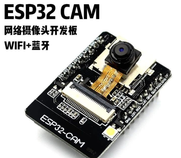
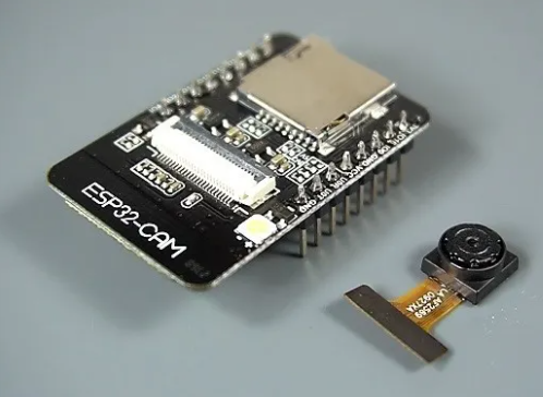
ESP32-CAM摄像头开发板
-
USB转串口下载器
-
杜邦连接线若干

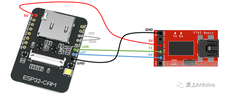
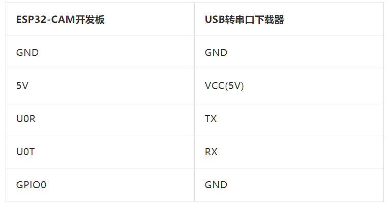
注意:GPIO0连接GND(下拉)的作用是让ESP32-CAM进入下载启动模式,这个模式里,才能利用Arduino IDE给ESP32编程,否则IDE会报错,代码烧录完成后,我们需要断开GPIO0和GND的连接,让ESP32进入正常的内存启动模式。
配置ESP32环境
https://www.cnblogs.com/kekeoutlook/p/14082790.html
样例1-wifi网页采集图像
在上传之前,还要修改代码中的wifi热点的名称和密码,请根据您自己的情况修改:
const char* ssid = "REPLACE_WITH_YOUR_SSID";//改成你自己的WiFi名称
const char* password = "REPLACE_WITH_YOUR_PASSWORD"; //改成你自己的WiFi密码
完整代码
/*********
  Rui Santos
  Complete project details at https://RandomNerdTutorials.com/esp32-cam-video-streaming-web-server-camera-home-assistant/

  IMPORTANT!!!
   - Select Board "AI Thinker ESP32-CAM"
   - GPIO 0 must be connected to GND to upload a sketch
   - After connecting GPIO 0 to GND, press the ESP32-CAM on-board RESET button to put your board in flashing mode

  Permission is hereby granted, free of charge, to any person obtaining a copy
  of this software and associated documentation files.

  The above copyright notice and this permission notice shall be included in all
  copies or substantial portions of the Software.
*********/

#include "esp_camera.h"
#include <WiFi.h>
#include "esp_timer.h"
#include "img_converters.h"
#include "Arduino.h"
#include "fb_gfx.h"
#include "soc/soc.h" //disable brownout problems
#include "soc/rtc_cntl_reg.h"  //disable brownout problems
#include "esp_http_server.h"

//Replace with your network credentials
const char* ssid = "dongdong";//改成你自己的WiFi名称  无线路由器
const char* password = "love123456";//改成你自己的WiFi密码 无线路由器

#define PART_BOUNDARY "123456789000000000000987654321"

// This project was tested with the AI Thinker Model, M5STACK PSRAM Model and M5STACK WITHOUT PSRAM
#define CAMERA_MODEL_AI_THINKER
//#define CAMERA_MODEL_M5STACK_PSRAM
//#define CAMERA_MODEL_M5STACK_WITHOUT_PSRAM

// Not tested with this model
//#define CAMERA_MODEL_WROVER_KIT

#if defined(CAMERA_MODEL_WROVER_KIT)
  #define PWDN_GPIO_NUM    -1
  #define RESET_GPIO_NUM   -1
  #define XCLK_GPIO_NUM    21
  #define SIOD_GPIO_NUM    26
  #define SIOC_GPIO_NUM    27

  #define Y9_GPIO_NUM      35
  #define Y8_GPIO_NUM      34
  #define Y7_GPIO_NUM      39
  #define Y6_GPIO_NUM      36
  #define Y5_GPIO_NUM      19
  #define Y4_GPIO_NUM      18
  #define Y3_GPIO_NUM       5
  #define Y2_GPIO_NUM       4
  #define VSYNC_GPIO_NUM   25
  #define HREF_GPIO_NUM    23
  #define PCLK_GPIO_NUM    22

#elif defined(CAMERA_MODEL_M5STACK_PSRAM)
  #define PWDN_GPIO_NUM     -1
  #define RESET_GPIO_NUM    15
  #define XCLK_GPIO_NUM     27
  #define SIOD_GPIO_NUM     25
  #define SIOC_GPIO_NUM     23

  #define Y9_GPIO_NUM       19
  #define Y8_GPIO_NUM       36
  #define Y7_GPIO_NUM       18
  #define Y6_GPIO_NUM       39
  #define Y5_GPIO_NUM        5
  #define Y4_GPIO_NUM       34
  #define Y3_GPIO_NUM       35
  #define Y2_GPIO_NUM       32
  #define VSYNC_GPIO_NUM    22
  #define HREF_GPIO_NUM     26
  #define PCLK_GPIO_NUM     21

#elif defined(CAMERA_MODEL_M5STACK_WITHOUT_PSRAM)
  #define PWDN_GPIO_NUM     -1
  #define RESET_GPIO_NUM    15
  #define XCLK_GPIO_NUM     27
  #define SIOD_GPIO_NUM     25
  #define SIOC_GPIO_NUM     23

  #define Y9_GPIO_NUM       19
  #define Y8_GPIO_NUM       36
  #define Y7_GPIO_NUM       18
  #define Y6_GPIO_NUM       39
  #define Y5_GPIO_NUM        5
  #define Y4_GPIO_NUM       34
  #define Y3_GPIO_NUM       35
  #define Y2_GPIO_NUM       17
  #define VSYNC_GPIO_NUM    22
  #define HREF_GPIO_NUM     26
  #define PCLK_GPIO_NUM     21

#elif defined(CAMERA_MODEL_AI_THINKER)
  #define PWDN_GPIO_NUM     32
  #define RESET_GPIO_NUM    -1
  #define XCLK_GPIO_NUM      0
  #define SIOD_GPIO_NUM     26
  #define SIOC_GPIO_NUM     27

  #define Y9_GPIO_NUM       35
  #define Y8_GPIO_NUM       34
  #define Y7_GPIO_NUM       39
  #define Y6_GPIO_NUM       36
  #define Y5_GPIO_NUM       21
  #define Y4_GPIO_NUM       19
  #define Y3_GPIO_NUM       18
  #define Y2_GPIO_NUM        5
  #define VSYNC_GPIO_NUM    25
  #define HREF_GPIO_NUM     23
  #define PCLK_GPIO_NUM     22
#else
  #error "Camera model not selected"
#endif

static const char* _STREAM_CONTENT_TYPE = "multipart/x-mixed-replace;boundary=" PART_BOUNDARY;
static const char* _STREAM_BOUNDARY = "
--" PART_BOUNDARY "
";
static const char* _STREAM_PART = "Content-Type: image/jpeg
Content-Length: %u

";

httpd_handle_t stream_httpd = NULL;

static esp_err_t stream_handler(httpd_req_t *req){
  camera_fb_t * fb = NULL;
  esp_err_t res = ESP_OK;
  size_t _jpg_buf_len = 0;
  uint8_t * _jpg_buf = NULL;
  char * part_buf[64];

  res = httpd_resp_set_type(req, _STREAM_CONTENT_TYPE);
  if(res != ESP_OK){
    return res;
  }

  while(true){
    fb = esp_camera_fb_get();
    if (!fb) {
      Serial.println("Camera capture failed");
      res = ESP_FAIL;
    } else {
      if(fb->width > 400){
        if(fb->format != PIXFORMAT_JPEG){
          bool jpeg_converted = frame2jpg(fb, 80, &_jpg_buf, &_jpg_buf_len);
          esp_camera_fb_return(fb);
          fb = NULL;
          if(!jpeg_converted){
            Serial.println("JPEG compression failed");
            res = ESP_FAIL;
          }
        } else {
          _jpg_buf_len = fb->len;
          _jpg_buf = fb->buf;
        }
      }
    }
    if(res == ESP_OK){
      size_t hlen = snprintf((char *)part_buf, 64, _STREAM_PART, _jpg_buf_len);
      res = httpd_resp_send_chunk(req, (const char *)part_buf, hlen);
    }
    if(res == ESP_OK){
      res = httpd_resp_send_chunk(req, (const char *)_jpg_buf, _jpg_buf_len);
    }
    if(res == ESP_OK){
      res = httpd_resp_send_chunk(req, _STREAM_BOUNDARY, strlen(_STREAM_BOUNDARY));
    }
    if(fb){
      esp_camera_fb_return(fb);
      fb = NULL;
      _jpg_buf = NULL;
    } else if(_jpg_buf){
      free(_jpg_buf);
      _jpg_buf = NULL;
    }
    if(res != ESP_OK){
      break;
    }
    //Serial.printf("MJPG: %uB
",(uint32_t)(_jpg_buf_len));
  }
  return res;
}

void startCameraServer(){
  httpd_config_t config = HTTPD_DEFAULT_CONFIG();
  config.server_port = 80;

  httpd_uri_t index_uri = {
    .uri       = "/",
    .method    = HTTP_GET,
    .handler   = stream_handler,
    .user_ctx  = NULL
  };

  //Serial.printf("Starting web server on port: '%d'
", config.server_port);
  if (httpd_start(&stream_httpd, &config) == ESP_OK) {
    httpd_register_uri_handler(stream_httpd, &index_uri);
  }
}

void setup() {
  WRITE_PERI_REG(RTC_CNTL_BROWN_OUT_REG, 0); //disable brownout detector

  Serial.begin(115200);
  Serial.setDebugOutput(false);

  camera_config_t config;
  config.ledc_channel = LEDC_CHANNEL_0;
  config.ledc_timer = LEDC_TIMER_0;
  config.pin_d0 = Y2_GPIO_NUM;
  config.pin_d1 = Y3_GPIO_NUM;
  config.pin_d2 = Y4_GPIO_NUM;
  config.pin_d3 = Y5_GPIO_NUM;
  config.pin_d4 = Y6_GPIO_NUM;
  config.pin_d5 = Y7_GPIO_NUM;
  config.pin_d6 = Y8_GPIO_NUM;
  config.pin_d7 = Y9_GPIO_NUM;
  config.pin_xclk = XCLK_GPIO_NUM;
  config.pin_pclk = PCLK_GPIO_NUM;
  config.pin_vsync = VSYNC_GPIO_NUM;
  config.pin_href = HREF_GPIO_NUM;
  config.pin_sscb_sda = SIOD_GPIO_NUM;
  config.pin_sscb_scl = SIOC_GPIO_NUM;
  config.pin_pwdn = PWDN_GPIO_NUM;
  config.pin_reset = RESET_GPIO_NUM;
  config.xclk_freq_hz = 20000000;
  config.pixel_format = PIXFORMAT_JPEG;

  if(psramFound()){
    config.frame_size = FRAMESIZE_UXGA;
    config.jpeg_quality = 10;
    config.fb_count = 2;
  } else {
    config.frame_size = FRAMESIZE_SVGA;
    config.jpeg_quality = 12;
    config.fb_count = 1;
  }

  // Camera init
  esp_err_t err = esp_camera_init(&config);
  if (err != ESP_OK) {
    Serial.printf("Camera init failed with error 0x%x", err);
    return;
  }
  // Wi-Fi connection
  WiFi.begin(ssid, password);
  while (WiFi.status() != WL_CONNECTED) {
    delay(500);
    Serial.print(".");
  }
  Serial.println("");
  Serial.println("WiFi connected");

  Serial.print("Camera Stream Ready! Go to: http://");
  Serial.print(WiFi.localIP());

  // Start streaming web server
  startCameraServer();
}

void loop() {
  delay(1);
}
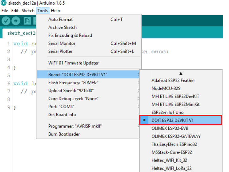
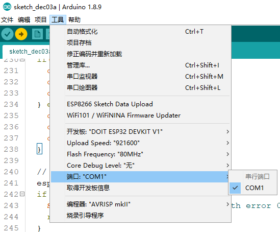
然后,在Tools(工具)>Board(开发板)选项里选择AI-Thinker ESP32-CAM。在Tools(工具)>Port(端口)选择正确的串口,最后上传代码。
控制代码烧录成功后,我们需要把GPIO0针脚和GND的连接断开,然后重新给ESP32-CAM上电。
然后打开Arduino IDE的串口监视器,选择115200波特率。再按一下ESP32-CAM上电RST按键。若一切正常,网络摄像头的IP就会打印在串口监视器上。
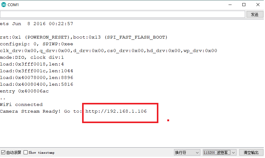
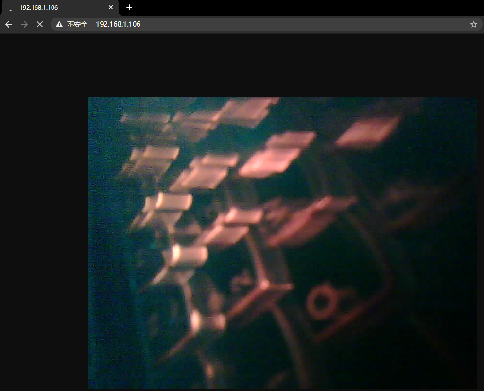
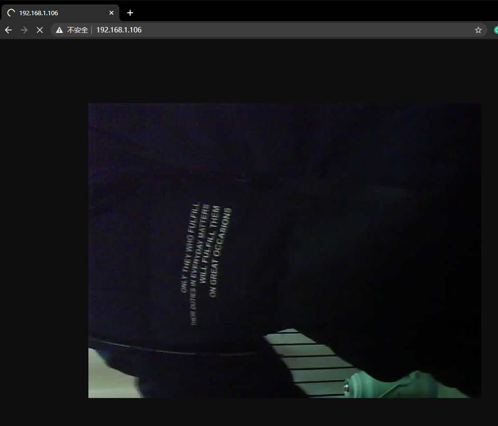
有了网络摄像头的IP,我们在同一网络内的任意一台电脑或者手机的浏览器地址栏里输入这个IP地址,就可以直接浏览了
一次只能一个设备访问
不是很实时
画质一般般
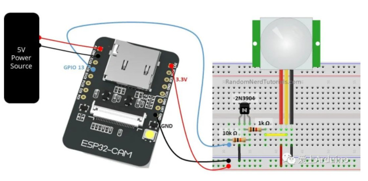
样例2 引脚低电平触发存图
GPIO13号引脚低电平触发拍照,可以用一根导线拔插GND引脚模拟
上电自动检测内存卡,无所有名字,最好是英文,每次触发自动保存
内存卡格式化

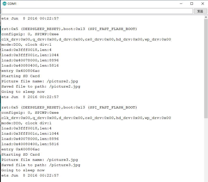
多试几次,然后断电取下Micro SD卡,如果一切正常的话,用电脑读取Micro SD卡时,应该能看见保存的照片。

画质一般般
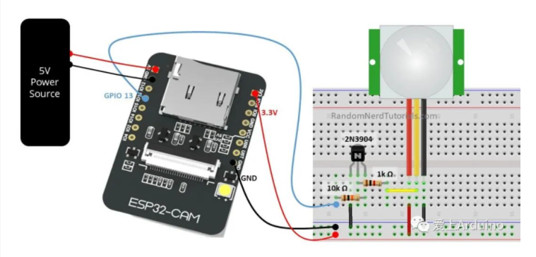
上图我们可以看到整个项目的流程图:
-
为了省电,ESP32-CAM默认处于深度睡眠(Deep Sleep)模式并开启外部唤醒(External Wake Up)。
-
当检测到移动物体,PIR传感器发送信号唤醒ESP32-CAM,ESP32-CAM立即拍照并且把照片存到Micro-SD存储卡里。
-
ESP32-CAM随后再次进入深度睡眠模式,直到下次被唤醒。
/*********
  Rui Santos
  Complete project details at https://RandomNerdTutorials.com/esp32-cam-pir-motion-detector-photo-capture/

  IMPORTANT!!!
   - Select Board "AI Thinker ESP32-CAM"
   - GPIO 0 must be connected to GND to upload a sketch
   - After connecting GPIO 0 to GND, press the ESP32-CAM on-board RESET button to put your board in flashing mode

  Permission is hereby granted, free of charge, to any person obtaining a copy
  of this software and associated documentation files.
  The above copyright notice and this permission notice shall be included in all
  copies or substantial portions of the Software.
*********/

#include "esp_camera.h"
#include "Arduino.h"
#include "FS.h"                // SD Card ESP32
#include "SD_MMC.h"            // SD Card ESP32
#include "soc/soc.h"           // Disable brownour problems
#include "soc/rtc_cntl_reg.h"  // Disable brownour problems
#include "driver/rtc_io.h"
#include <EEPROM.h>            // read and write from flash memory
// define the number of bytes you want to access
#define EEPROM_SIZE 1

RTC_DATA_ATTR int bootCount = 0;


// Pin definition for CAMERA_MODEL_AI_THINKER
#define PWDN_GPIO_NUM     32
#define RESET_GPIO_NUM    -1
#define XCLK_GPIO_NUM      0
#define SIOD_GPIO_NUM     26
#define SIOC_GPIO_NUM     27
#define Y9_GPIO_NUM       35
#define Y8_GPIO_NUM       34
#define Y7_GPIO_NUM       39
#define Y6_GPIO_NUM       36
#define Y5_GPIO_NUM       21
#define Y4_GPIO_NUM       19
#define Y3_GPIO_NUM       18
#define Y2_GPIO_NUM        5
#define VSYNC_GPIO_NUM    25
#define HREF_GPIO_NUM     23
#define PCLK_GPIO_NUM     22

int pictureNumber = 0;

void setup() {
  WRITE_PERI_REG(RTC_CNTL_BROWN_OUT_REG, 0); //disable brownout detector
  Serial.begin(115200);

  Serial.setDebugOutput(true);

  camera_config_t config;
  config.ledc_channel = LEDC_CHANNEL_0;
  config.ledc_timer = LEDC_TIMER_0;
  config.pin_d0 = Y2_GPIO_NUM;
  config.pin_d1 = Y3_GPIO_NUM;
  config.pin_d2 = Y4_GPIO_NUM;
  config.pin_d3 = Y5_GPIO_NUM;
  config.pin_d4 = Y6_GPIO_NUM;
  config.pin_d5 = Y7_GPIO_NUM;
  config.pin_d6 = Y8_GPIO_NUM;
  config.pin_d7 = Y9_GPIO_NUM;
  config.pin_xclk = XCLK_GPIO_NUM;
  config.pin_pclk = PCLK_GPIO_NUM;
  config.pin_vsync = VSYNC_GPIO_NUM;
  config.pin_href = HREF_GPIO_NUM;
  config.pin_sscb_sda = SIOD_GPIO_NUM;
  config.pin_sscb_scl = SIOC_GPIO_NUM;
  config.pin_pwdn = PWDN_GPIO_NUM;
  config.pin_reset = RESET_GPIO_NUM;
  config.xclk_freq_hz = 20000000;
  config.pixel_format = PIXFORMAT_JPEG;

  pinMode(4, INPUT);
  digitalWrite(4, LOW);
  rtc_gpio_hold_dis(GPIO_NUM_4);

  if(psramFound()){
    config.frame_size = FRAMESIZE_UXGA; // FRAMESIZE_ + QVGA|CIF|VGA|SVGA|XGA|SXGA|UXGA
    config.jpeg_quality = 10;
    config.fb_count = 2;
  } else {
    config.frame_size = FRAMESIZE_SVGA;
    config.jpeg_quality = 12;
    config.fb_count = 1;
  }

  // Init Camera
  esp_err_t err = esp_camera_init(&config);
  if (err != ESP_OK) {
    Serial.printf("Camera init failed with error 0x%x", err);
    return;
  }

  Serial.println("Starting SD Card");

  delay(500);
  if(!SD_MMC.begin()){
    Serial.println("SD Card Mount Failed");
    //return;
  }

  uint8_t cardType = SD_MMC.cardType();
  if(cardType == CARD_NONE){
    Serial.println("No SD Card attached");
    return;
  }

  camera_fb_t * fb = NULL;

  // Take Picture with Camera
  fb = esp_camera_fb_get();
  if(!fb) {
    Serial.println("Camera capture failed");
    return;
  }
  // initialize EEPROM with predefined size
  EEPROM.begin(EEPROM_SIZE);
  pictureNumber = EEPROM.read(0) + 1;

  // Path where new picture will be saved in SD Card
  String path = "/picture" + String(pictureNumber) +".jpg";

  fs::FS &fs = SD_MMC;
  Serial.printf("Picture file name: %s
", path.c_str());

  File file = fs.open(path.c_str(), FILE_WRITE);
  if(!file){
    Serial.println("Failed to open file in writing mode");
  }
  else {
    file.write(fb->buf, fb->len); // payload (image), payload length
    Serial.printf("Saved file to path: %s
", path.c_str());
    EEPROM.write(0, pictureNumber);
    EEPROM.commit();
  }
  file.close();
  esp_camera_fb_return(fb);

  delay(1000);

  // Turns off the ESP32-CAM white on-board LED (flash) connected to GPIO 4
  pinMode(4, OUTPUT);
  digitalWrite(4, LOW);
  rtc_gpio_hold_en(GPIO_NUM_4);


  esp_sleep_enable_ext0_wakeup(GPIO_NUM_13, 0);

  Serial.println("Going to sleep now");
  delay(1000);
  esp_deep_sleep_start();
  Serial.println("This will never be printed");
}

void loop() {

}
样例3-ESP32-CAM获取的图像显示在OLED上面
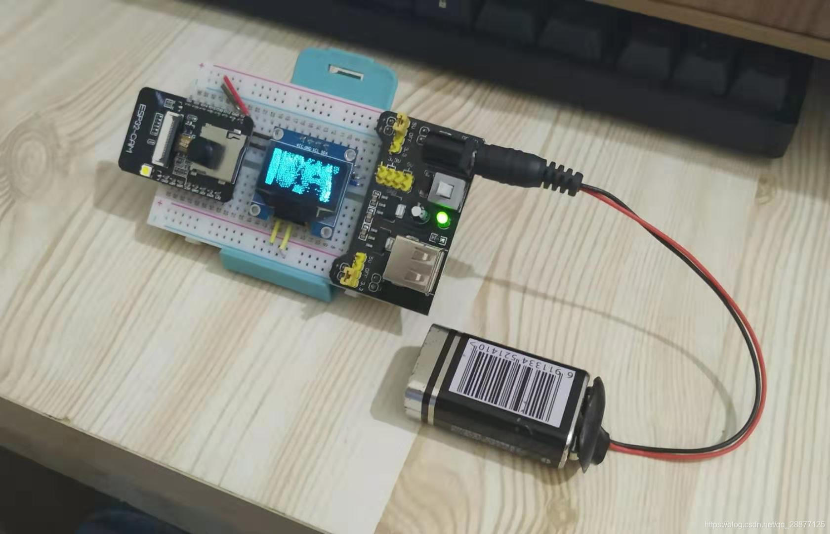

IIC - SSD1306
ESP32-cam IIC 引脚:
SCL:PIN14
SDA:PIN15
#include "esp_camera.h"
#include "SSD1306.h"

// clk:14; sda:15
SSD1306 display(0x3c, 15, 14);

#define SCREEN_WIDTH 128 // OLED显示宽度,以像素为单位
#define SCREEN_HEIGHT 64

#define PWDN_GPIO_NUM     32
#define RESET_GPIO_NUM    -1
#define XCLK_GPIO_NUM      0
#define SIOD_GPIO_NUM     26
#define SIOC_GPIO_NUM     27
#define Y9_GPIO_NUM       35
#define Y8_GPIO_NUM       34
#define Y7_GPIO_NUM       39
#define Y6_GPIO_NUM       36
#define Y5_GPIO_NUM       21
#define Y4_GPIO_NUM       19
#define Y3_GPIO_NUM       18
#define Y2_GPIO_NUM        5
#define VSYNC_GPIO_NUM    25
#define HREF_GPIO_NUM     23
#define PCLK_GPIO_NUM     22

static camera_config_t camera_config = {
	.pin_pwdn = PWDN_GPIO_NUM,
	.pin_reset = RESET_GPIO_NUM,
	.pin_xclk = XCLK_GPIO_NUM,
	.pin_sscb_sda = SIOD_GPIO_NUM,
	.pin_sscb_scl = SIOC_GPIO_NUM,
	.pin_d7 = Y9_GPIO_NUM,
	.pin_d6 = Y8_GPIO_NUM,
	.pin_d5 = Y7_GPIO_NUM,
	.pin_d4 = Y6_GPIO_NUM,
	.pin_d3 = Y5_GPIO_NUM,
	.pin_d2 = Y4_GPIO_NUM,
	.pin_d1 = Y3_GPIO_NUM,
	.pin_d0 = Y2_GPIO_NUM,
	.pin_vsync = VSYNC_GPIO_NUM,
	.pin_href = HREF_GPIO_NUM,
	.pin_pclk = PCLK_GPIO_NUM,

	.xclk_freq_hz = 20000000,
	.ledc_timer = LEDC_TIMER_0,
	.ledc_channel = LEDC_CHANNEL_0,

	.pixel_format = PIXFORMAT_GRAYSCALE,
	.frame_size = FRAMESIZE_QQVGA2,
	.jpeg_quality = 12,
	.fb_count = 1,
};

byte x,y;
uint8_t oldpixel, newpixel;
int quanterror;

esp_err_t camera_init()
{
	//initialize the camera
	esp_err_t err = esp_camera_init(&camera_config);
	if (err != ESP_OK)
	{
		Serial.print("Camera Init Failed");
		return err;
	}
	sensor_t * s = esp_camera_sensor_get();
	//initial sensors are flipped vertically and colors are a bit saturated
	if (s->id.PID == OV2640_PID)
	{
		s->set_vflip(s, 1);//flip it back
		s->set_brightness(s, 1);//up the blightness just a bit
		s->set_contrast(s, 1);
	}
	Serial.print("Camera Init OK");
	return ESP_OK;
}

void my_camera_show(void)
{
	camera_fb_t *fb = esp_camera_fb_get();
	int i = 0;
	for(y = 0; y < SCREEN_HEIGHT; y++)
	{
		for(x = 0;x < SCREEN_WIDTH; x++)
		{
			oldpixel = fb->buf[i]; //保持原始的灰度值
			newpixel = (255*(oldpixel >> 7)); //门槛值128
			fb->buf[i] = newpixel; //缓冲区现在是单通道,0或255
			// floyd-steignburg抖动算法
			quanterror = oldpixel - newpixel; //像素之间的误差
			//将此错误分发给相邻像素:
			//右
			if(x < SCREEN_WIDTH-1)//边界检查...
			{
				fb->buf[(x + 1)+(y * SCREEN_WIDTH)] += ((quanterror * 7)>> 4);
			}
			// 左下
			if((x > 1) && (y < SCREEN_HEIGHT-1))//边界检查...
			{
				fb->buf [(x-1)+((y + 1)* SCREEN_WIDTH)] == ((quanterror * 3)>> 4);
			}
			//下
			if(y < 63)//边界检查...
			{
				fb->buf [(x)+((y + 1)* SCREEN_WIDTH)] == ((quanterror * 5)>> 4);
			}
			// 右下
			if((x < SCREEN_WIDTH-1) && (y < SCREEN_HEIGHT-1))//边界检查...
			{
				fb->buf [(x + 1) + ((y + 1)* SCREEN_WIDTH)] == (quanterror >> 4);
			}
			// 画这个像素
			switch(fb->buf[i]%2)
			{
			case 0:
				display.setColor(BLACK);
				break;
			case 1:
				display.setColor(WHITE);
				break;
			case 2:
				display.setColor(INVERSE);
				break;
			}
			display.setPixel(x, y);
			i++;
		}
	}
	display.display();
	esp_camera_fb_return(fb);
}


void setup()
{
	Serial.begin(115200);
	display.init();
	camera_init();
	Serial.setDebugOutput(true);
	Serial.println();
	Serial.print("sys is 1...");
	Serial.print("sys is running!");
}

void loop()
{
   my_camera_show();
}