一 使用OpenCV/python进行双目测距
https://www.cnblogs.com/zhiyishou/p/5767592.html
二 如何从深度图计算包络获取独立障碍物
https://blog.csdn.net/weixin_38285131/article/details/88541374
https://blog.csdn.net/keith_bb/article/details/70194073
一 使用OpenCV/python进行双目测距
https://www.cnblogs.com/zhiyishou/p/5767592.html
标定

由于摄像头目前是我们手动进行定位的,我们现在还不知道两张图像与世界坐标之间的耦合关系,所以下一步要进行的是标定,用来确定分别获取两个摄像头的内部参数,并且根据两个摄像头在同一个世界坐标下的标定参数来获取立体参数。注:不要使用OpenCV自带的自动calbration,其对棋盘的识别率极低,使用Matlab的Camera Calibration Toolbox更为有效,具体细节请看:摄像机标定和立体标定
同时从两个摄像头获取图片
import cv2
import time

AUTO = True  # 自动拍照,或手动按s键拍照
INTERVAL = 2 # 自动拍照间隔

cv2.namedWindow("left")
cv2.namedWindow("right")
cv2.moveWindow("left", 0, 0)
cv2.moveWindow("right", 400, 0)
left_camera = cv2.VideoCapture(0)
right_camera = cv2.VideoCapture(1)

counter = 0
utc = time.time()
pattern = (12, 8) # 棋盘格尺寸
folder = "./snapshot/" # 拍照文件目录

def shot(pos, frame):
    global counter
    path = folder + pos + "_" + str(counter) + ".jpg"

    cv2.imwrite(path, frame)
    print("snapshot saved into: " + path)

while True:
    ret, left_frame = left_camera.read()
    ret, right_frame = right_camera.read()

    cv2.imshow("left", left_frame)
    cv2.imshow("right", right_frame)

    now = time.time()
    if AUTO and now - utc >= INTERVAL:
        shot("left", left_frame)
        shot("right", right_frame)
        counter += 1
        utc = now

    key = cv2.waitKey(1)
    if key == ord("q"):
        break
    elif key == ord("s"):
        shot("left", left_frame)
        shot("right", right_frame)
        counter += 1

left_camera.release()
right_camera.release()
cv2.destroyWindow("left")
cv2.destroyWindow("right")
下面是我拍摄的样本之一,可以肉眼看出来这两个摄像头成像都不是水平的,这更是需要标定的存在的意义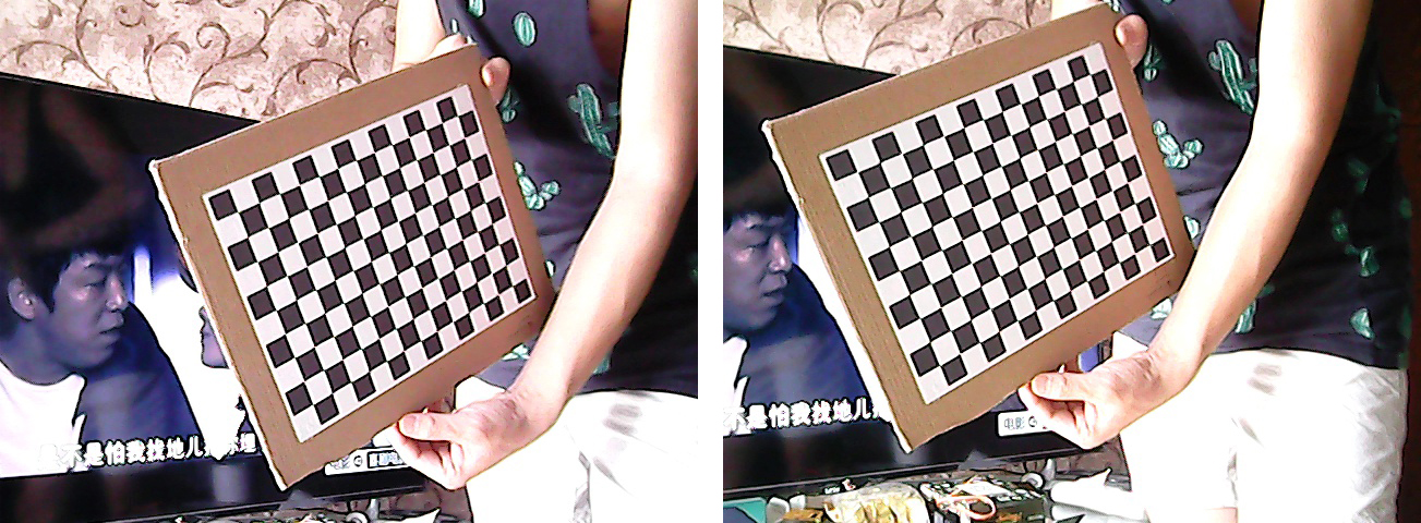
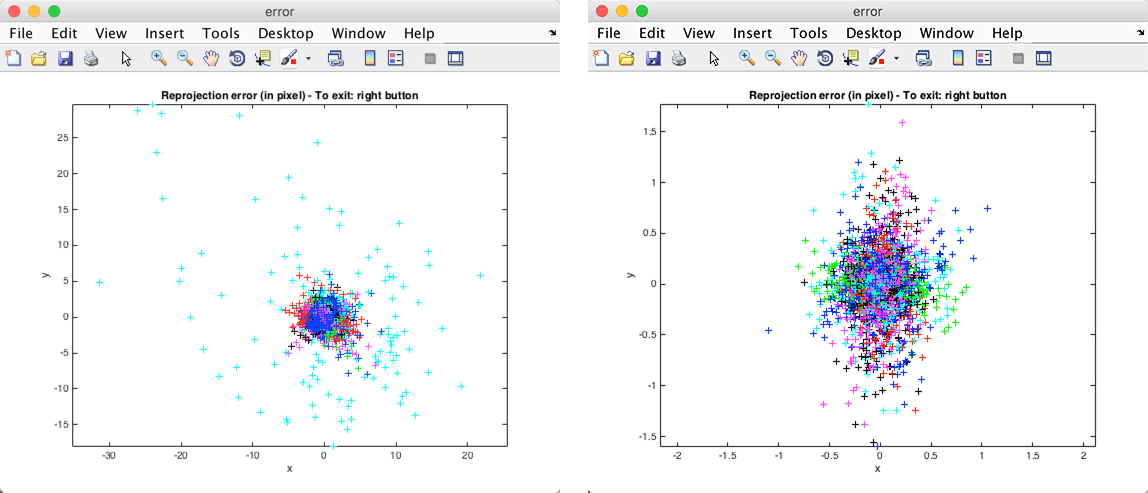
在进行标定的过程中,要注意的是在上面标定方法中没有提到的是,单个标定后,要对标定的数据进行错误分析(Analyse Error),如左图,是我对左摄像头的标定结果分析。图中天蓝色点明显与大部分点不聚敛,所以有可能是标定时对这个图片标定出现的错误,要重新标定,在该点上点击并获取其图片名称索引,对其重新标定后,右图的结果看起来还是比较满意的
在进行完立体标定后,我们将得到如下的数据:
Stereo calibration parameters after optimization:

Intrinsic parameters of left camera:

Focal Length:          fc_left = [ 824.93564   825.93598 ]  [ 8.21112   8.53492 ]
Principal point:       cc_left = [ 251.64723   286.58058 ]  [ 13.92642   9.11583 ]
Skew:             alpha_c_left = [ 0.00000 ]  [ 0.00000  ]   => angle of pixel axes = 90.00000  0.00000 degrees
Distortion:            kc_left = [ 0.23233   -0.99375   0.00160   0.00145  0.00000 ]  [ 0.05659   0.30408   0.00472   0.00925  0.00000 ]

Intrinsic parameters of right camera:

Focal Length:          fc_right = [ 853.66485   852.95574 ]  [ 8.76773   9.19051 ]
Principal point:       cc_right = [ 217.00856   269.37140 ]  [ 10.40940   9.47786 ]
Skew:             alpha_c_right = [ 0.00000 ]  [ 0.00000  ]   => angle of pixel axes = 90.00000  0.00000 degrees
Distortion:            kc_right = [ 0.30829   -1.61541   0.01495   -0.00758  0.00000 ]  [ 0.06567   0.55294   0.00547   0.00641  0.00000 ]

Extrinsic parameters (position of right camera wrt left camera):

Rotation vector:             om = [ 0.01911   0.03125  -0.00960 ]  [ 0.01261   0.01739  0.00112 ]
Translation vector:           T = [ -70.59612   -2.60704  18.87635 ]  [ 0.95533   0.79030  5.25024 ]
应用标定数据
我们使用如下的代码来将其配置到python中,上面的参数都是手动填写至下面的内容中的,这样免去保存成文件再去读取,在托运填写的时候要注意数据的对应位置。
# filename: camera_configs.py
import cv2
import numpy as np

left_camera_matrix = np.array([[824.93564, 0., 251.64723],
                               [0., 825.93598, 286.58058],
                               [0., 0., 1.]])
left_distortion = np.array([[0.23233, -0.99375, 0.00160, 0.00145, 0.00000]])


right_camera_matrix = np.array([[853.66485, 0., 217.00856],
                                [0., 852.95574, 269.37140],
                                [0., 0., 1.]])
right_distortion = np.array([[0.30829, -1.61541, 0.01495, -0.00758, 0.00000]])

om = np.array([0.01911, 0.03125, -0.00960]) # 旋转关系向量
R = cv2.Rodrigues(om)[0]  # 使用Rodrigues变换将om变换为R
T = np.array([-70.59612, -2.60704, 18.87635]) # 平移关系向量

size = (640, 480) # 图像尺寸

# 进行立体更正
R1, R2, P1, P2, Q, validPixROI1, validPixROI2 = cv2.stereoRectify(left_camera_matrix, left_distortion,
                                                                  right_camera_matrix, right_distortion, size, R,
                                                                  T)
# 计算更正map
left_map1, left_map2 = cv2.initUndistortRectifyMap(left_camera_matrix, left_distortion, R1, P1, size, cv2.CV_16SC2)
right_map1, right_map2 = cv2.initUndistortRectifyMap(right_camera_matrix, right_distortion, R2, P2, size, cv2.CV_16SC2)
这样,我们得到了左右摄像头的两个map,并得到了立体的Q,这些参数都将应用于下面的转换成深度图中
转换成深度图
import numpy as np
import cv2
import camera_configs

cv2.namedWindow("left")
cv2.namedWindow("right")
cv2.namedWindow("depth")
cv2.moveWindow("left", 0, 0)
cv2.moveWindow("right", 600, 0)
cv2.createTrackbar("num", "depth", 0, 10, lambda x: None)
cv2.createTrackbar("blockSize", "depth", 5, 255, lambda x: None)
camera1 = cv2.VideoCapture(0)
camera2 = cv2.VideoCapture(1)

# 添加点击事件,打印当前点的距离
def callbackFunc(e, x, y, f, p):
    if e == cv2.EVENT_LBUTTONDOWN:
        print threeD[y][x]

cv2.setMouseCallback("depth", callbackFunc, None)

while True:
    ret1, frame1 = camera1.read()
    ret2, frame2 = camera2.read()

    if not ret1 or not ret2:
        break

    # 根据更正map对图片进行重构
    img1_rectified = cv2.remap(frame1, camera_configs.left_map1, camera_configs.left_map2, cv2.INTER_LINEAR)
    img2_rectified = cv2.remap(frame2, camera_configs.right_map1, camera_configs.right_map2, cv2.INTER_LINEAR)

    # 将图片置为灰度图,为StereoBM作准备
    imgL = cv2.cvtColor(img1_rectified, cv2.COLOR_BGR2GRAY)
    imgR = cv2.cvtColor(img2_rectified, cv2.COLOR_BGR2GRAY)

    # 两个trackbar用来调节不同的参数查看效果
    num = cv2.getTrackbarPos("num", "depth")
    blockSize = cv2.getTrackbarPos("blockSize", "depth")
    if blockSize % 2 == 0:
        blockSize += 1
    if blockSize < 5:
        blockSize = 5

    # 根据Block Maching方法生成差异图(opencv里也提供了SGBM/Semi-Global Block Matching算法,有兴趣可以试试)
    stereo = cv2.StereoBM_create(numDisparities=16*num, blockSize=blockSize)
    disparity = stereo.compute(imgL, imgR)

    disp = cv2.normalize(disparity, disparity, alpha=0, beta=255, norm_type=cv2.NORM_MINMAX, dtype=cv2.CV_8U)
    # 将图片扩展至3d空间中,其z方向的值则为当前的距离
    threeD = cv2.reprojectImageTo3D(disparity.astype(np.float32)/16., camera_configs.Q)

    cv2.imshow("left", img1_rectified)
    cv2.imshow("right", img2_rectified)
    cv2.imshow("depth", disp)

    key = cv2.waitKey(1)
    if key == ord("q"):
        break
    elif key == ord("s"):
        cv2.imwrite("./snapshot/BM_left.jpg", imgL)
        cv2.imwrite("./snapshot/BM_right.jpg", imgR)
        cv2.imwrite("./snapshot/BM_depth.jpg", disp)

camera1.release()
camera2.release()
cv2.destroyAllWindows()
下面则是一附成像图,最右侧的为生成的disparity图,按照上面的代码,在图上点击则可以读取到该点的距离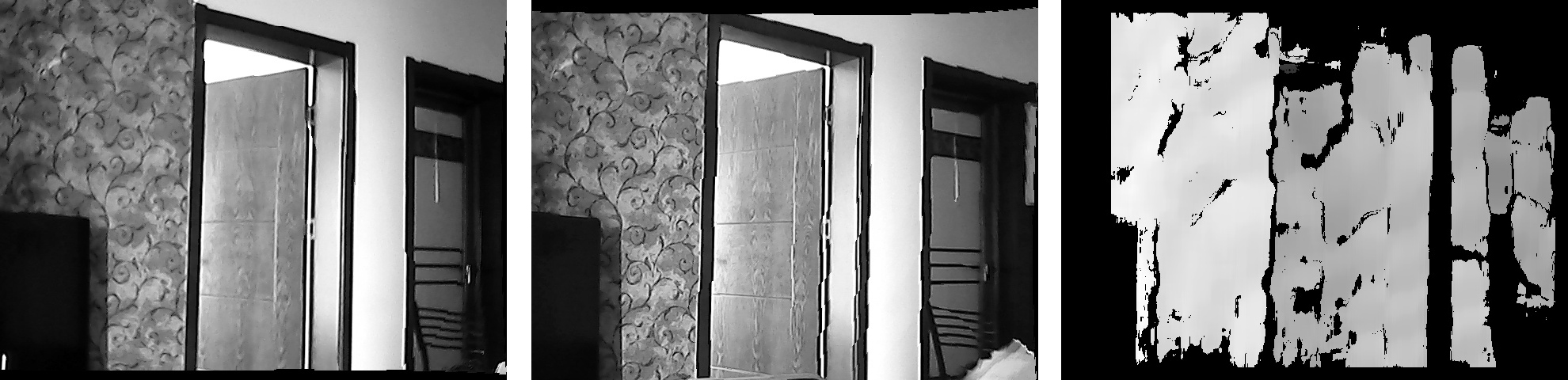
二 如何从深度图计算包络获取独立障碍物
https://blog.csdn.net/weixin_38285131/article/details/88541374
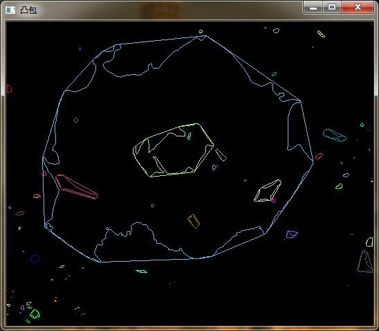
opencv学习(四十一)之寻找凸包convexHull()
//阈值化
	int threshValue = Otsu(result1);
	Mat local;
	threshold(result1, local, 20,255,CV_THRESH_BINARY);
	imshow("二值化", local);
	imwrite("thresholded.jpg", local);

	//计算凸包
	cout << "计算凸包和轮廓....." << endl;
	vector<vector<Point> > contours;
	vector<Vec4i> hierarchy;
	findContours(local, contours, hierarchy, CV_RETR_EXTERNAL, CV_CHAIN_APPROX_SIMPLE, Point(0, 0));
	/// 对每个轮廓计算其凸包
	vector<vector<Point> >hull(contours.size());
	vector<vector<Point> > result;
	for (int i = 0; i < contours.size(); i++)
	{
		convexHull(Mat(contours[i]), hull[i], false);

	}
	cout << "轮廓凸包绘制......" << endl;
	/// 绘出轮廓及其凸包
	Mat drawing = Mat::zeros(local.size(), CV_8UC3);
	for (int i = 0; i < contours.size(); i++)
	{
		if (contourArea(contours[i]) < 500)//面积小于area的凸包,可忽略
			continue;
		result.push_back(hull[i]);
		Scalar color = Scalar(0,0,255);
		drawContours(drawing, contours, i, color, 1, 8, vector<Vec4i>(), 0, Point());
		drawContours(drawing, hull, i, color, 1, 8, vector<Vec4i>(), 0, Point());
	}
	imshow("contours", drawing);
	imwrite("contours.jpg", drawing);

	//计算每一个凸包的位置和高度(也就是物体高度和位置)
	cout << "计算物体位置....." << endl;
	Point pt[100000];
	Moments moment;//矩
	vector<Vec3f>Center;//创建保存物体重心的向量
	Vec3f Point3v;//三维坐标点
	for (int i = 0; i >= 0; i = hierarchy[i][0])//读取每一个轮廓求取重心
	{
		Mat temp(contours.at(i));
		Scalar color(0, 0, 255);
		moment = moments(temp, false);
		if (contourArea(contours[i]) < 500)//面积小于area的凸包,可忽略
			continue;
		if (moment.m00 != 0)//除数不能为0
		{
			pt[i].x = cvRound(moment.m10 / moment.m00);//计算重心横坐标
			pt[i].y = cvRound(moment.m01 / moment.m00);//计算重心纵坐标
		}
		//重心坐标
		Point3v = xyz.at<Vec3f>(pt[i].y, pt[i].x);
		Center.push_back(Point3v);//将重心坐标保存到Center向量中
	}

	//统计物体高度
	Point p1, p2;//分别是物体最高点和最低点的位置
	float height,width;//物体高度
	Vec3f point1,point2;//物体的最高点和最低点的实际高度
	vector<float>all_height;
	vector<float>all_width;
	for (int i = 0; i < result.size(); i++)
	{
		sort(hull[i].begin(), hull[i].end(), sortRuleY);
		p1 = hull[i][0];
		p2 = hull[i][hull[i].size() - 1];
		point1 = xyz.at<Vec3f>(p1.y, p1.x);
		point2 = xyz.at<Vec3f>(p2.y, p2.x);
		height = abs(point1[1] - point2[1]);

		sort(hull[i].begin(), hull[i].end(), sortRuleX);
		p1 = hull[i][0];
		p2 = hull[i][hull[i].size() - 1];
		point1 = xyz.at<Vec3f>(p1.y, p1.x);
		point2 = xyz.at<Vec3f>(p2.y, p2.x);
		width = abs(point1[0] - point2[0]);
		all_height.push_back(height);
		all_width.push_back(width);
	}

	//输出物体的位置和高度
	if (all_height.size() == Center.size()&&all_height.size()!=0)
	{
		for (int i = 0; i < Center.size(); i++)
		{
			cout << "障碍物坐标:" << Center[i] << "  " << "障碍物高度:" << all_height[i] <<"障碍物宽度:"<<all_width[i]<< endl;
		}
	}
	else
	{
		cout << "位置和高度数量不一致或者大小全为0!" << endl;
	}