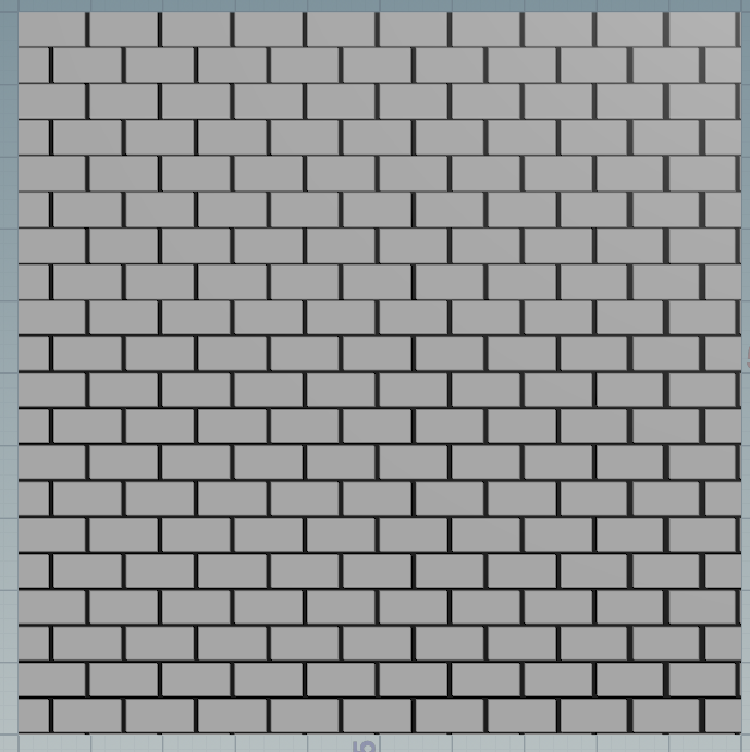
Ready:
VScode + glslCanvas + glslLinter + Shadering languages support + glslang
Ref:
>>tutorial
>>2dboxsdf
NDC:
uniform vec2 u_resolution;
vec2 P = (gl_FragCoord.xy / u_resolution - vec2(0.5)) * 2.0;
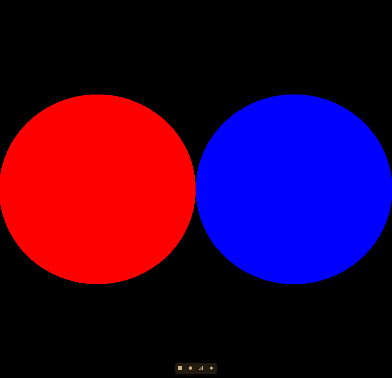
1:sphere

#ifdef GL_ES
precision mediump float;
#endif

uniform vec2 u_resolution;
const float e = 1e-8;

struct Shape{
    float sdf;
    vec3 color;
};

Shape combine_sdf(Shape a, Shape b){
    Shape temp;
    temp.sdf = min(a.sdf,b.sdf);
    temp.color = a.color * float(a.sdf<=0.0) +  b.color * float(b.sdf<=0.0) ;
    return temp;
}

float circle_sdf (vec2 pos,vec2 center,float radius)
{
    return length(pos-center) - radius;
}


void main()
{
    float radius = 0.5;
    vec2 P = (gl_FragCoord.xy / u_resolution - vec2(0.5)) * 2.0;
    Shape cle01= Shape(circle_sdf(P,vec2(-0.5, 0.0), radius), vec3(1,0,0));
    Shape cle02= Shape(circle_sdf(P,vec2(0.5,  0.0), radius), vec3(0,0,1));
    Shape scene = combine_sdf(cle01,cle02);
    vec3 color = float(scene.sdf <=0.0) * scene.color;
    gl_FragColor = vec4(color, 1.0);

}
2:rectangle

#ifdef GL_ES
precision mediump float;
#endif

uniform vec2 u_resolution;
const float e = 1e-8;

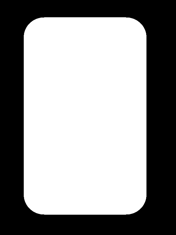
float Rectangle(vec2 p, vec2 rec, float radius){
    vec2 q = abs(p) - rec;
    float outDis = length(max(q,0.0));
    float inDis = min(max(q.x,q.y),0.0);
    return outDis + inDis - radius;
}


void main()
{
    float radius = 0.5;
    vec2 P = (gl_FragCoord.xy / u_resolution - vec2(0.5)) * 2.0;
    float box = Rectangle(P, vec2(0.2,0.4), 0.1);
    vec3 L = vec3( float(box<=0.0));
    gl_FragColor = vec4(L, 1.0);

}
3:polygonShape:

#ifdef GL_ES
precision mediump float;
#endif

uniform vec2 u_resolution;
const float e = 1e-8;
const float PI = 3.1415926535;


float polygonShape(vec2 p,float radius, float sides){

    float angle = atan(p.x, p.y);
    float slice = PI*2.0 / sides;
    return cos(floor(0.5+angle/slice)*slice - angle) * length(p)- radius;
}


void main()
{
    float radius = 0.2;
    vec2 P = (gl_FragCoord.xy / u_resolution - vec2(0.5))*2.0;


    // Render Simple scene
    //vec3 L = float(scene.sdf <=0.0) * scene.Cd;
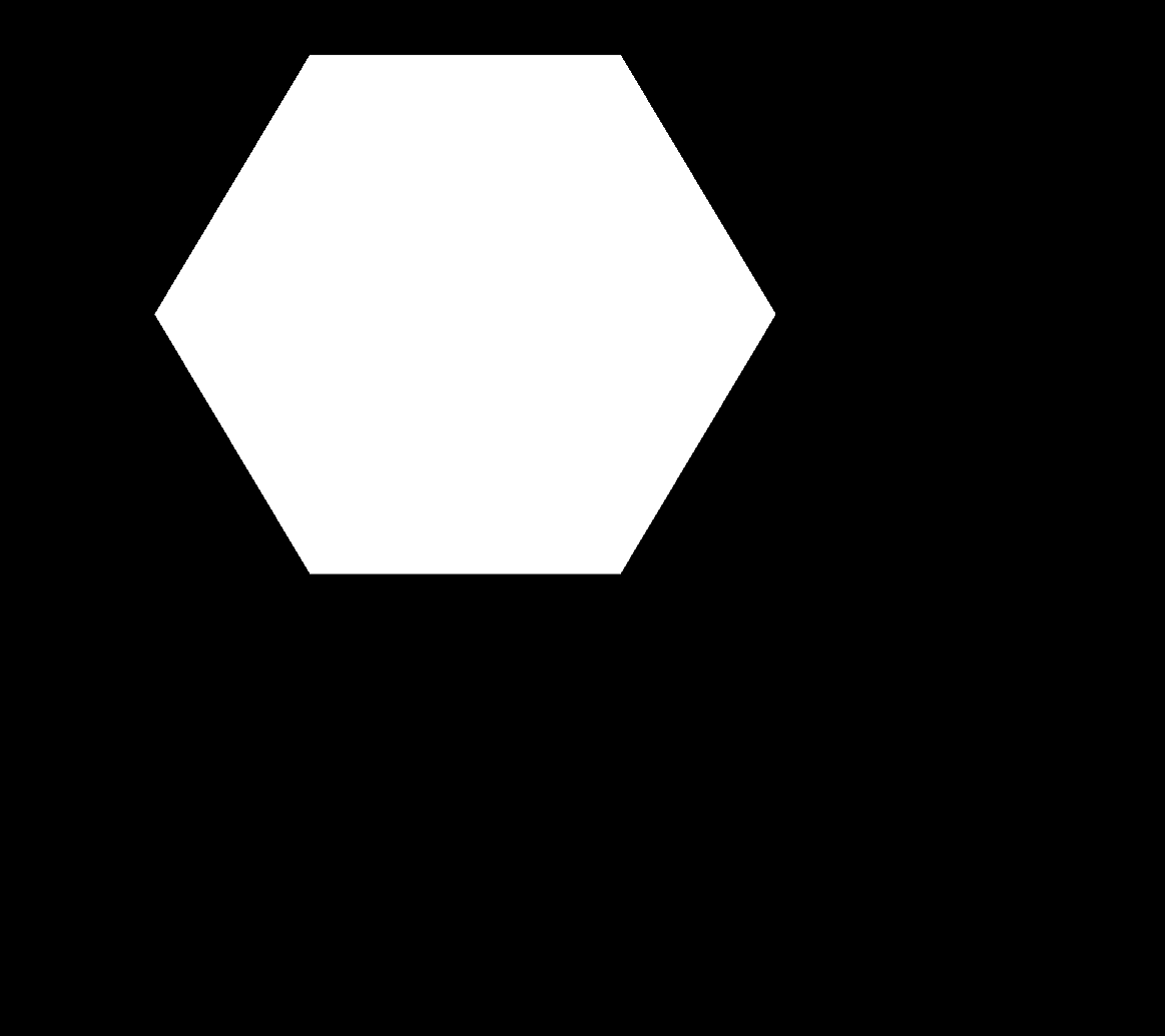
    float sdf = polygonShape(P,0.2,5.0);
    vec3 L = vec3( float(sdf<=.0) );
    // Out Radiance
    gl_FragColor = vec4(L,1.0);

}

4,u_time:

#ifdef GL_ES
precision mediump float;
#endif

uniform vec2 u_resolution;
uniform float u_time;
const float e = 1e-8;
const float PI = 3.1415926535;


float polygonShape(vec2 p,float radius, float sides){

    float angle = atan(p.x, p.y);
    float slice = PI*2.0 / sides;
    return cos(floor(0.5+angle/slice)*slice - angle) * length(p)- radius;
}


void main()
{
    float radius = 0.2;
    vec2 P = gl_FragCoord.xy / u_resolution - vec2(0.5);


    // Render Simple scene
    //vec3 L = float(scene.sdf <=0.0) * scene.Cd;
    float ofx = cos(u_time*5.0)*0.2;
    float ofy = sin(u_time*5.0)*0.2;
    vec2 offset = vec2(ofx,ofy);
    float sdf = polygonShape(P+offset,0.2,6.0);
    vec3 L = vec3( float(sdf<=.0) );
    // Out Radiance
    gl_FragColor = vec4(L,1.0);

}
simple cos sin offset the position by time:
float ofx = cos(u_time*5.0)*0.2;
float ofy = sin(u_time*5.0)*0.2;
vec2 offset = vec2(ofx,ofy);
float sdf = polygonShape(P+offset,0.2,6.0);
GLSL是列向量为主


#ifdef GL_ES
precision mediump float;
#endif

uniform vec2 u_resolution;
uniform float u_time;
const float e = 1e-8;
const float PI = 3.1415926535;


float polygonShape(vec2 p,float radius, float sides){

    float angle = atan(p.x, p.y);
    float slice = PI*2.0 / sides;
    return cos(floor(0.5+angle/slice)*slice - angle) * length(p)- radius;
}
float combineSDF(float s1,float s2){
    return min(s1,s2);
}

// column major
mat2 rotate(float angle){
    return mat2(vec2(cos(angle),sin(angle)),vec2(-sin(angle),cos(angle)));
}
// same as above
mat2 rotate2(float angle){
    return mat2(cos(angle),sin(angle),-sin(angle),cos(angle));
}


void main()
{
    float radius = 0.2;
    vec2 P = (gl_FragCoord.xy / u_resolution - vec2(0.5)) * 2.0;


    float angle = 45.0;

    // Red Rectangle
    vec2 offset1 = vec2(0.5,0.0); // move to left
    mat2 rot1 = rotate(PI/180.0 * angle);  // method 1
    vec3 Cd1 = vec3(1,0,0);
    float sdf1 = polygonShape(rot1* (P + offset1),0.2,4.0);

    // Green Rectangle
    vec2 offset2 = vec2(-0.5,0.0); // move to right
    vec3 Cd2 = vec3(0,1,0);
    mat2 rot2 = rotate2(PI/180.0 * angle);   // In this case, use rotate method 2 same method 1
    float sdf2 = polygonShape(rot2*(P + offset2),0.2,4.0);


    // combie sdf & color
    float sdf = combineSDF(sdf1,sdf2);
    vec3 color = Cd1 * float(sdf1<=0.0) +  Cd2 * float(sdf2<=0.0);

    vec3 L = vec3( color * float(sdf<=0.0) );
    // Out Radiance
    gl_FragColor = vec4(L,1.0);

}
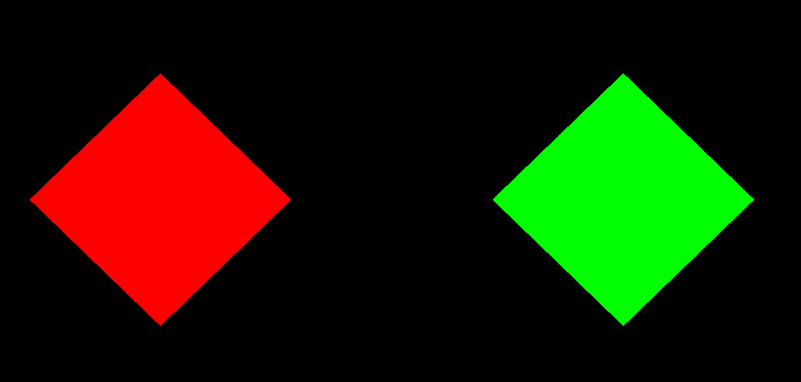
理解其中的变换:
注意其中的mat2*(P + offset),因为P是sdf sample point,相当于基坐标。
再3D 软件都是RST or SRT 这样的顺序,在这里一定要搞清楚是变换的采样基所以先在基坐标系P+offset下绘制出来Rectangle,然后再旋转,顺序是TR
加强理解变换:
还有以中简单的理解你加的offset 是世界空间加的,如果用下面代码:
float sdf2 = polygonShape(rot2*P + rot2*offset2,0.2,4.0);
把P转换到rot2的空间,把offset2转换到rot2空间,空间一致相加没问题。
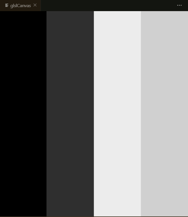
6,用uv空间做floor效果:

#ifdef GL_ES
precision mediump float;
#endif

uniform vec2 u_resolution;
uniform float u_time;
const float e = 1e-8;
const float PI = 3.1415926535;
const float speed = 3.0;


void main()
{
    float radius = 0.2;
    //vec2 P = (gl_FragCoord.xy / u_resolution - vec2(0.5)) * 2.0;
    vec2 P = gl_FragCoord.xy / u_resolution ;

    float data = sin(floor(P.x*4.0) + u_time*speed);
    //data = clamp(data,0.0,1.0);
    vec3 L = vec3( data );
    // Out Radiance
    gl_FragColor = vec4(L,1.0);

}
7,理解在这种模式下得缩放:

#ifdef GL_ES
precision mediump float;
#endif

uniform vec2 u_resolution;
uniform float u_time;
const float e = 1e-8;
const float PI = 3.1415926535;
const float speed = 3.0;

float circle_sdf (vec2 pos,vec2 center,float radius)
{
    return length(pos-center) - radius;
}
mat2 scale(float sx ,float sy){
    return mat2(sx,0.0,0.0,sy);
}

void main()
{
    float radius = 0.2;
    vec2 P = (gl_FragCoord.xy / u_resolution - vec2(0.5)) * 2.0;

    //vec2 P = gl_FragCoord.xy / u_resolution ;
    mat2 scaleMat = scale(2.0,2.0);
    P = scaleMat * P;
    float sdf = circle_sdf( P,vec2(0),0.5);

    float data = float(sdf<=e);

    vec3 L = vec3( data );
    // Out Radiance
    gl_FragColor = vec4(L,1.0);

}
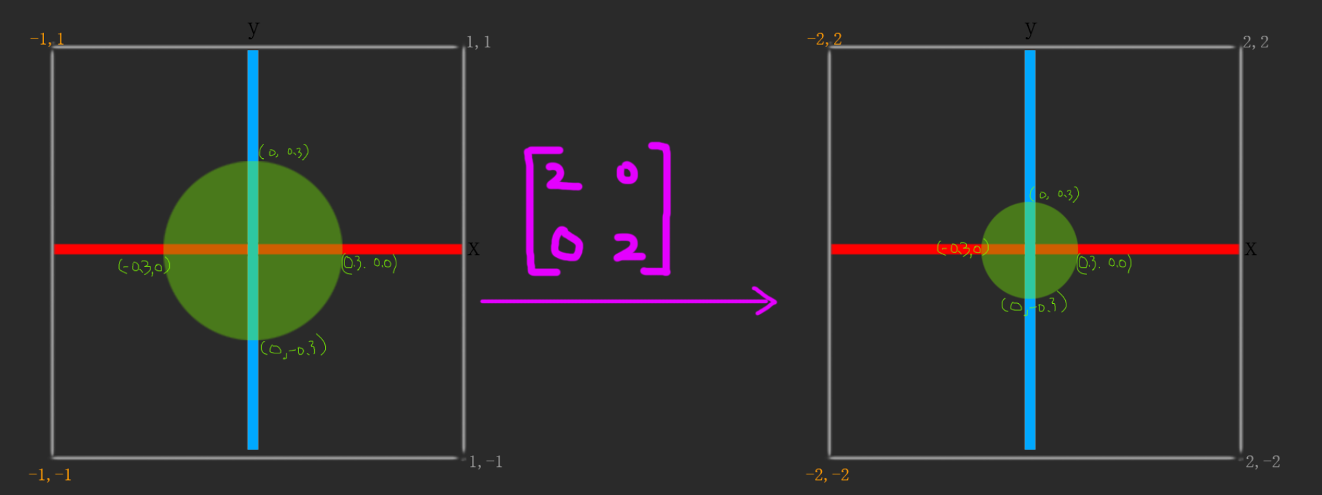
mat2 scaleMat = scale(2.0,2.0);
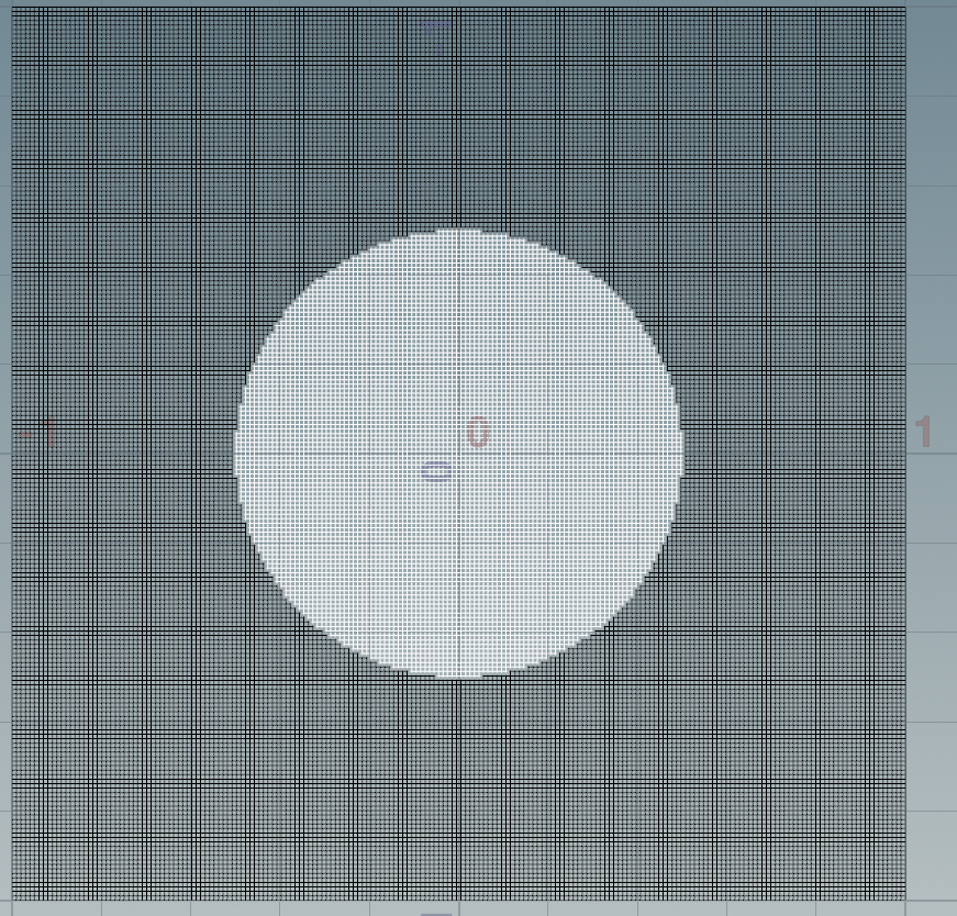
按理说用上面得矩阵,图像应该是放大。为什么会呈现出缩放效果:
原因跟rotate一样,因为变换得基坐标,所以就会导致在基坐标放大了,画得图就会变小:
Houdini理解一样:
不应用矩阵时候:
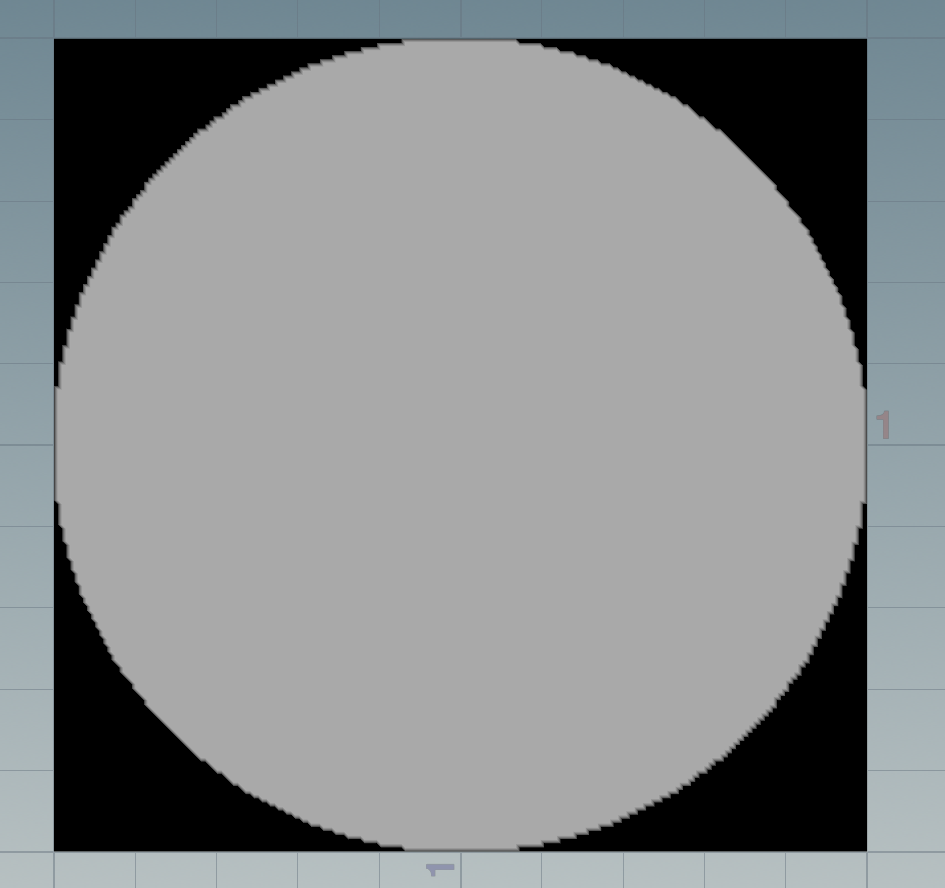
应用后:
8:

#ifdef GL_ES
precision mediump float;
#endif

uniform vec2 u_resolution;
uniform float u_time;

const float expvalue =4.0;
const float light_intensity = 0.1;
const int numpoints = 3;


void main(){

    vec2 uv = gl_FragCoord.xy / u_resolution; // uv pos
    vec2 P = (uv - vec2(0.5) ) * 2.0;

    vec3 L = vec3(0.0);

    for(int i = 0; i <numpoints ; i++){

        float per_angle = float(360) /  float(numpoints) ;
        float angle = per_angle * float(i) + u_time * 40.0;
        float lg_x = sin(  radians(angle) )*0.5;
        float lg_y = cos( radians(angle ) )*0.6;

        vec2 newpos = vec2(lg_x,lg_y);
        float data = light_intensity*light_intensity / pow(length(P + newpos),expvalue);

        L += vec3(data);
    }


    gl_FragColor = vec4(L,1.0);

}

9,下面可能用houdini测试。

float fract(float x){
    return x - floor(x);
}

float step(float edge;float x){
    if(x < edge){
        return 0;
    }
    return 1;
}

float bsize = chf("bricksize");
float bpct = chf("brickPct");
float xscale = chf("xscale");
float yscale = chf("yscale");

vector2 P = set(@P.x, @P.z); // gen plane at x z , so we assume and translate to x y plane
P.x /= xscale;
P.y /= yscale;

P/= bsize;

if (fract(P.y * 0.5) > 0.5)
    P.x += .5;


P.x = fract(P.x);
P.y = fract(P.y);

P.x = step(P.x , bpct);
P.y = step(P.y , bpct);

@Cd = P.x * P.y;
