BACKGROUND
Many computing systems include a network interface card (NIC) to provide for communications with other systems and devices over a network. In a computing system running multiple operating systems (OSs) on multiple virtual machines, each OS typically needs to communicate with its own NIC. Thus, multiple NICs are required to be installed on the computing system to support the multiple OSs running in virtual machines. However, it may be uneconomical and perhaps impractical to install multiple NICs. In some instances, the computing system has no spare Peripheral Component Interconnect (PCI) or PCI Express (PCIE) slots to install additional NICs, or has no room in the specific form factor of the computing system. In other cases, the cost of additional NICs may be prohibitive for the overall cost of the computing system.
DETAILED DESCRIPTION
Embodiments of the present invention comprise a system and method for sharing one physical network interface card (NIC) device among multiple virtual machines (VMs) in a computing system. In embodiments of the present invention, one operating system (OS) called the Service OS, running in a first VM, controls access to the physical NIC and services communications requests from one or more other OSs, called Consumer OSs. A Consumer OS runs in another VM and interacts with a user of the computer system via an application program. The application program runs in the same VM as the Consumer OS. When the Consumer OS needs to communicate over the physical NIC device, the Consumer OS sends a network request packet to the Service OS. The Service OS interprets the network request packet and forwards the packet to the physical NIC. Hence, the Service OS virtualizes the NIC for the Consumer OS, without requiring the computing system to include a physical NIC for each Consumer OS.
In order to protect the virtualization of the physical NIC, in embodiments of the present invention the first VM running the Service OS may be executed within a Secure Enclave (SE) session within the processor package of the computing system. FIG. 1 is a diagram of a Secure Enclave session in a computing system according to an embodiment of the present invention. For purposes of explanation, portions of computing system 100 are shown in FIG. 1 in simplified form. Processor package 102 comprises one or more processing cores within a security perimeter. In one embodiment, the security perimeter may be the processor package boundary (shown as a thick line in FIG. 1). The processor package interfaces with memory 104 and platform control hub (PCH) 106. The PCH interfaces with one or more I/O devices 108. Implementation of a Secure Enclave capability involves providing several processor instructions which create the secure enclave and enforce isolation and provide protection of instruction execution and data access. Data and code outside of the processor package may be encrypted and integrity checked. Data and code inside of the processor package may be unencrypted and protected by a mode and cache protection mechanism. In an embodiment, data does not "leak" from the secure enclave. Microcode within the processor package saves the enclave state information inside the enclave for interrupts, exceptions, traps and Virtual Machine Manager (VMM) exits. The Secure Enclave capability is described in the PCT patent application entitled "Method and Apparatus to Provide Secure Application Execution" by Francis X. McKeen, et al., filed in the USPTO as a Receiving Office on Dec. 22, 2009, as PCT/US2009/069212, and incorporated herein by reference.

FIG. 2 is a diagram of a computing system illustrating multiple virtual machines according to an embodiment of the present invention. The computing system comprises computing platform 200, which comprises processor package 102, memory 104, PCH 106, and I/O devices 108 of FIG. 1, as well as other conventional components that are not shown. One of the I/O devices may be a NIC. System firmware, known as basic input/output system (BIOS) 202, executes on the computing platform starting at system boot time to identify, test, and initialize the computing platform components and to provide interfaces to computing platform hardware to software components of the computing system. In embodiments of the present invention supporting known virtualization technology, a virtual machine manager (VMM) may be executed immediately after the BIOS finishes initialization of the computing platform. The VMM supports the concurrent execution of multiple virtual machines on the computing platform. The VMM presents guest operating systems with a virtual platform and monitors the execution of the guest operating systems. In that way, multiple operating systems, including multiple instances of the same operating system, can share hardware resources. Unlike multitasking, which also allows applications to share hardware resources, the virtual machine approach using a VMM isolates failures in one operating system from other operating systems sharing the hardware. The VMM prepares the execution environment for VMs in the system. The VMM launches one or more VMs as required.
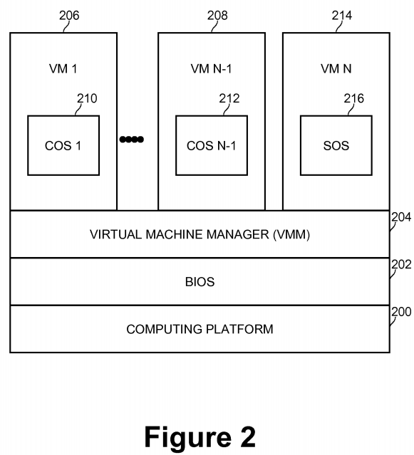
In embodiments of the present invention, multiple VMs may be launched and executed concurrently, and there may be at least two kinds of VMs. One kind of VM is a Service VM 214 running a Service OS (SOS) 216. The Service OS generally provides services to other OSs running in other VMs, and interacts with VMM 204to provide those services. A second kind of VM is a Consumer OS (COS) 210 (also called a Guest OS) running in a Consumer VM 206. The Consumer OS supports application programs (not shown in FIG. 2) interacting with a user of the computing system. The Consumer OS relies on services provided by VMM 204 and Service OS 216. Application programs running within a Consumer VM cannot directly interact with the Service OS running in the Service VM. In embodiments of the present invention, multiple Consumer VMs 1 206 to N-1 208 may be launched, running Consumer OSs 1 210 to N-1 212, respectively.
FIG. 3 is a diagram of a computing system illustrating network stacks for virtual machines according to an embodiment of the present invention. In an embodiment, in order to provide network services to application program 304 supported by one of the Consumer OSs such as COS 1 210 executing within Consumer VM 1206, VMM 204 (not shown in FIG. 3) creates a COS virtual NIC device 310. To the Consumer OS, this virtualized NIC device functions like a physical NIC device. A COS virtual NIC driver component 308 may be created within Consumer OS 1 210. COS virtual NIC driver 308 may be responsible for processing network requests from the upper level COS network stack 306 and responding with request results. When application program 304 requests I/O over the physical NIC device, the request may be processed by COS network stack 306, COS virtual NIC driver 308, and COS virtual NIC device 310. Responses processed by COS virtual NIC device310 may be forwarded back to the application program via COS virtual NIC driver 308 and COS network stack 306.
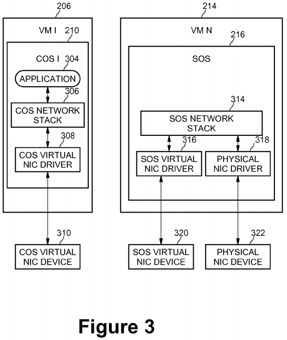
A corresponding Service OS (SOS) virtual NIC device 320 may be created for access by Service VM 214. A corresponding SOS virtual NIC driver 316 may also be created within Service OS 216 running in Service VM 214. A request by COS virtual NIC device 310 coupled to Consumer VM 206 may be forwarded for processing to SOS virtual NIC device 320 coupled to Service VM 214. The request may be handled by SOS virtual NIC device 320 and SOS network stack 314 within the Service OS. Since the Service OS interacts with physical NIC device 322, the Service OS may control implementation of the request by physical NIC driver 318 and physical NIC device 322. Responses to the request may flow in the opposite direction, from physical NIC device 322 to physical NIC driver 318 through SOS network stack 314, SOS virtual NIC driver 316, and SOS virtual NIC device 320 back to the Service OS. Thus, Consumer OS 210 has the illusion that it is communicating with physical NIC device 322.
When Service OS 216 is run within a Secure Enclave session, I/O requests involving physical NIC device 322 may be protected from malicious processing by application programs in the Consumer VM or other programs running within a Consumer OS. At system initialization time, or whenever a physical NIC device is added to the computing system, a Secure Enclave session may be started to protect access to the physical NIC device.
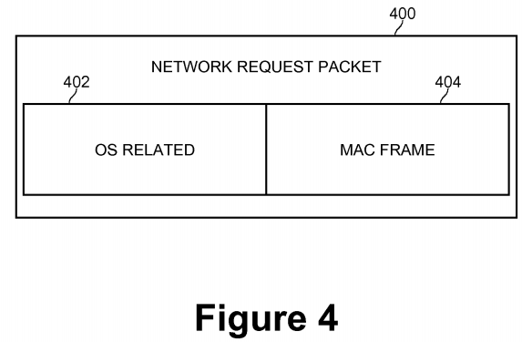
An I/O request in the form of a network request packet arriving at COS virtual NIC driver 308 from application program 304 via COS network stack 306 has been processed by network protocol layers such as Transmission Control Protocol (TCP), User Datagram Protocol (UDP), and Internet Protocol (IP). The network request packet contains information necessary for transmission over a network, such that the packet may be provided to the physical NIC driver to transmit on the physical NIC device. FIG. 4 is a diagram of a network request packet according to an embodiment of the present invention. Network request packet 400 comprises OS related information 402, and Media Access Control (MAC) frame information 404. OS related information 402 contains information and/or parameters used by network stack drivers or NIC device drivers. This part will be not transmitted on the network interface of the physical NIC device and might not be understood by the Service OS, so this part of the network request packet may be ignored. The MAC frame information is the actual content sent on the network interface (e.g., the basic transmission unit on the Ethernet network media).
According to embodiments of the present invention, there is no physical NIC device directly available for the Consumer OS, therefore, COS virtual NIC driver 308 relies on components of the Service VM and the VMM to send the packet. The VMM notifies the Service OS when there are packets to process and creates a shared memory area for use in exchanging data between the Consumer VM and Service VMs. The shared memory area may be made visible to both the Consumer OS and the Service OS, so that the virtual NIC driver in each VM can access the packets and process them accordingly. In one embodiment, the shared memory may be implemented within memory 104.
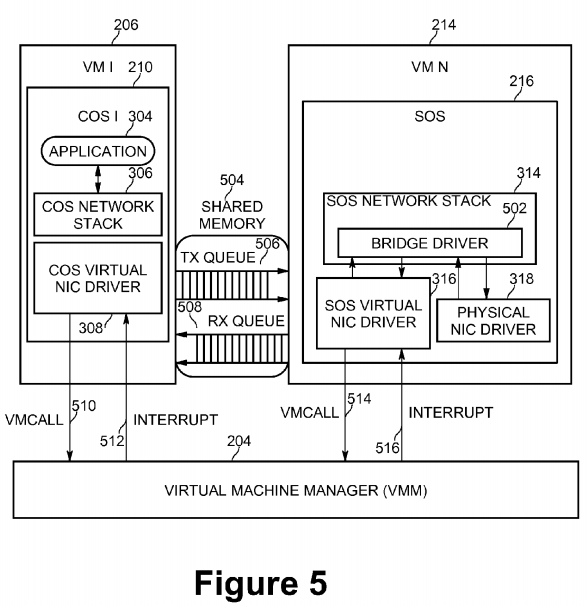
FIG. 5 is a diagram of shared memory and communications between virtual machines according to an embodiment of the present invention. COS virtual NIC driver 308 may extract the MAC frame 404 from the network request packet, allocate a memory block from the shared memory, copy the MAC frame into the shared memory block, and append this block into a designated transmission (TX) queue 506. The TX queue 506 exists in the shared memory to help manage outgoing MAC frames. In the reverse path, when there are packets received by the physical NIC device 322 that are managed by the Service OS, the components of the Service OS (i.e., physical NIC driver 318, SOS network stack 314, and SOS virtual NIC driver 316) extract the MAC frame, copy the MAC frame contents into a free memory block in shared memory, and append the block into a reception (RX) queue 508.
COS virtual NIC driver 308 may inform the Service OS that there are MAC frames that need to be transmitted in the following manner. In embodiments of the present invention, a message notification mechanism using known virtualization technology may be used. VMM 204 may operate as the intermediary between the Consumer OS and the Service OS, and may notify the appropriate OS as required.
For example, when Customer OS 1 210 wants to communicate with Service OS 216, the Customer OS may execute a privileged instruction named VMCALL 510. The VMCALL instruction is used to exit the current VM environment and call selected services in VMM 204. Those services may be offered by the handler of the VMCALL instruction in the VMM. The VMCALL handler (not shown in FIG. 5) may check the input parameters of the VMCALL and determine whether the VMM should inform the Service OS. If so, the VMM logs the message, and returns control to the Customer OS. Since VMM is always a running process within the computing system, the VMM attempts to inform the Service OS using Interrupt 516 when the VMM turns to the time slot for Service OS execution. Similarly, when the Service OS wants to communicate with the Customer OS, the Service OS may execute VMCALL 514 and the VMM may notify the Customer OS using Interrupt 512.
On the Service OS side, since the Service OS is an agent of the Customer OS for network transmission and reception, embodiments of the present invention provide two driver components to support this agency arrangement. One is SOS virtual NIC driver 316. The other is bridge driver component 502. SOS virtual NIC driver316 in the Service OS is in charge of collecting outgoing MAC frames from the Customer OS via transmission TX queue 506 in shared memory 504 and passing them to the physical NIC driver 318 through the bridge driver. The bridge driver also receives incoming packets from physical NIC driver 318 that are intended for the Customer OS and puts the packets into the reception RX queue 508 in shared memory 504 for access by the Customer OS. In detail, when SOS virtual NIC driver 316 is informed by VMM 204 that there are outgoing packets in transmission TX queue 506, the SOS virtual NIC driver in the Service OS extracts the MAC frame from the transmission TX queue, repackages the frame into a new network request packet, and commits the new packet to the SOS network stack 314. On the other hand, when SOS virtual NIC driver 316 receives packets from the SOS network stack that are headed to the Customer OS, the SOS virtual NIC driver removes the OS-related portion and puts the MAC frame into reception RX queue 508 for access by the Customer OS. This message notification method described may be used to inform the Customer OS to process the incoming packets.
In embodiments of the present invention, the bridge driver 502 implements a filter driver in the IP protocol layer, therefore the bridge driver checks all inbound packets from the physical NIC device via the physical NIC driver 318 and routes them to the correct destination. For example, if the bridge driver finds a packet received from SOS virtual NIC driver 316, the bridge driver forwards the packet to physical NIC driver 318. If the bridge driver finds a packet received from physical NIC driver 318, the bridge driver will check the IP address information in this packet and determine whether the packet should go to the Customer OS 210 or the Service OS 216. If the bridge driver determines this packet is to go to Customer OS 210, the bridge driver forwards the packet to the SOS virtual NIC driver 316, for further forwarding of the information to the Customer OS.
The destination of packets received from physical NIC driver 318 may be differentiated between Customer OS and Service OS in at least two methods. One method is that the Customer OS and the Service OS use different IP addresses, so that bridge driver 502 may refer to the IP address information inside the received network packet and determine which OS is the packet's receptor. A second method is that the Customer OS and the Service OS may use the same IP address, but use a different range of TCP or UDP ports. The first method may make the packet routing logic simple, but costs more IP address resources. The second method may save IP address resources, but may result in the packet routing logic within the bridge driver being more complex. The choice between these two methods depends on intended usage models and is an implementation decision.
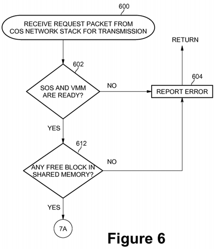
FIGS. 6 and 7 are flow diagrams of network request packet transmission processing according to an embodiment of the present invention. At block 600, when a network request packet is received from the Customer OS (COS) network stack 306 for transmission over the physical NIC device, a check may be made at 602 by the COS virtual NIC driver 308 to determine if the Service OS (SOS) 216 and the VMM 204 are ready. If either the Service OS or the VMM (or both) are not ready, then processing continues with block 604 where an error message may be reported and control may be returned back to the Customer OS. If the Service OS and the VMM are ready at block 602, then a check may be made at block 612, if any free blocks are available in shared memory. If no free blocks are available, processing continues with block 604 where an error may be reported. If free blocks are available, processing continues with block 702 on FIG. 7.
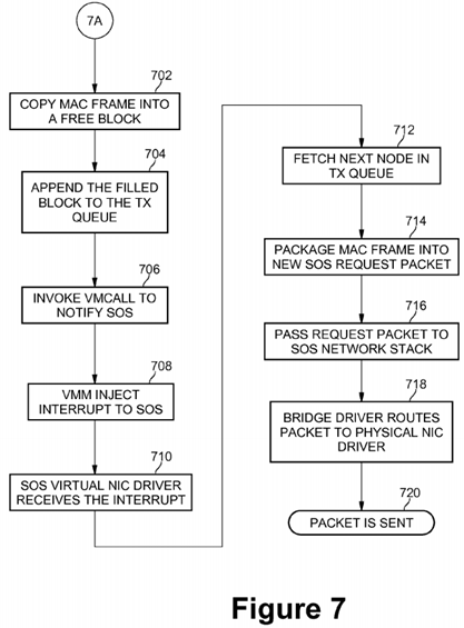
At block 702 of FIG. 7, COS virtual NIC driver 308 copies the MAC frame of the network request packet into a free block in shared memory 504. At block 704, the newly filled block may be appended to the transmission queue TX 506. The COS virtual NIC driver 308 then invokes the VMCALL instruction 510 at block 706to notify the Service OS 216 via the VMM 204. At block 708, the VMM injects an interrupt 516 to the Service OS. In response, SOS virtual NIC driver 316 within the Service OS receives the interrupt at block 710 and fetches the next node in the transmission queue TX 506 at block 712. At block 714, the SOS virtual NIC driver 316 packages the MAC frame information from the next node in the transmission queue TX into a new Service OS request packet. SOS virtual NIC driver 316 then passes the new Service OS request packet to Service OS network stack 314 at block 716. Next, at block 718 bridge driver 502 routes the new Service OS request packet to physical NIC driver 318. The new Service OS request packet is sent over the network interface by the physical NIC driver at block 720.
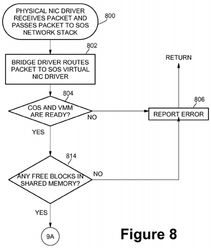
FIGS. 8 and 9 are flow diagrams of network request packet reception processing according to an embodiment of the present invention. At block 800, physical NIC driver 318 receives at least one network packet from the physical NIC device 322 and passes the network packet to the SOS network stack 314 within the Service OS 216. At block 802, bridge driver 502 within network stack routes the incoming packet to the SOS virtual NIC driver 316 in the Service OS. A check may then be made at block 804 by the SOS virtual NIC driver 316 to determine if the Customer OS (COS) 210 and the VMM 204 are ready. If either the Customer OS or the VMM (or both) are not ready, then processing continues with block 806 where an error message may be reported and control may be returned back to the Service OS. If the Customer OS and VMM are ready, then at block 814, a check may be made if any free blocks are available in shared memory. If no free blocks are available, processing continues with block 806 and an error message may be reported. If free blocks are available, processing continues with block 902 on FIG. 9.

At block 902 of FIG. 9, SOS virtual NIC driver 316 copies the MAC frame of the received network packet into a free block in shared memory 504. At block 904, the newly filled block may be appended to the reception queue RX 508. The SOS virtual NIC driver 316 then invokes the VMCALL instruction 514 at block 906 to notify the Customer OS 210 via the VMM 204. At block 908, the VMM injects an interrupt 512 to the Customer OS. In response, COS virtual NIC driver 308 within the Customer OS receives the interrupt at block 910 and fetches the next node in the reception queue RX 508 at block 912. At block 914, the COS virtual NIC driver 308 packages the MAC frame information from the next node in the reception queue RX into a new Customer OS response packet. COS virtual NIC driver 308 then passes the new response packet to Customer OS network stack 306 at block 916, and onward to application program 304.
Thus, embodiments of the present invention may share one physical NIC device among multiple virtual machines when a user's application programs running in Customer OSs need access to the network. There is no need to install additional physical NIC devices.
One skilled in the art will recognize the option of implementing different schemes to provide multiple virtual machines secure access to a single physical NIC device—without deviating from the scope of the present invention. One skilled in the art will also recognize that the disclosed invention may be applied to different types of virtualized environments and virtualization systems, pure software or hardware-assisted, that may employ either partial or complete virtualization of computer systems or programming environments.
One skilled in the art will also recognize that the number of Customer OSs and corresponding Customer VMs may be greater than two and implementation dependent. Further, when two or more Customer VMs are concurrently running, one customer VM may be running one kind of OS (such as Microsoft Windows 7, for example) and another customer VM may be running another kind of OS (such as Linux, for example).