针对之前给出的直流电机调速基本模型,进行调速控制器设计。
在该基本模型中,模型PWMVoltageSource表示一个直流调压装置,接收来自控制器的正负10V的指令信号,正负10V的指令信号对应直流调压装置输出正负200V的电压,直流调压装置的时间常数为0.003秒。
model PWMVoltageSource
  extends TwoPin;
  InPort Command(n=1);

  parameter Time T = 0.003;
  parameter Voltage Vin = 200;

equation

    T*der(v)+ v = Vin*Command.signal[1]/10;

end PWMVoltageSource;
模型DCMotor表示一个直流电机:
model DCMotor                 "DC Motor"
  extends TwoPin;
  extends Rigid;
  OutPort SensorVelocity(n=1);
  OutPort SensorCurrent(n=1);
  parameter MomentOfInertia J"Total Inertia";
  parameter Resistance R"Armature Resistance";
  parameter Inductance L"Armature Inductance";
  parameter Real Kt"Torque Constant";
  parameter Real Ke"EMF Constant";

  AngularVelocity    w          "Angular velocity of motor";
  AngularAcceleration a          "Absolute angular acceleration of motor";
  Torque tau_motor;
  RotFlange_b    rotFlange_b;    // Rotational Flange_b

equation

  w = der(rotFlange_b.phi);
  a = der(w);
  v = R*i+Ke*w+L*der(i);
  tau_motor =  Kt*i;
  J*a = tau_motor + rotFlange_b.tau;
  SensorVelocity.signal[1] = w;
  SensorCurrent.signal[1] = i;
end DCMotor;
DCMotor具有一个电气端口和一个机械端口,以及两个反馈信号端口SensorVelocity(电机速度反馈信号)和SensorCurrent(电机电枢电流反馈信号)
CommandSignalGenerator是一个速度命令信号发生器,产生一个梯形速度信号。
block CommandSignalGenerator

  OutPort outPort(n=1);
  Real acc;

equation

   if time <= 1 then
     acc =60;
   elseif time <3 then
     acc = 0;
   elseif time <4 then
     acc = -60;
   else
     acc = 0;
   end if;

   der(outPort.signal[1]) = acc;

end CommandSignalGenerator;
该调速系统的系统模型为:
model DCMotorControlSystem

  Ground       ground1;
  Inertia      inertia1(J = 3, w(fixed = true));
  DCMotor      motor1(J = 1,R = 0.6,L = 0.01,Kt=1.8, Ke= 1.8,rotFlange_b(phi(fixed = true)));
  CommandSignalGenerator  sg1;
  Controller   con1;
  PWMVoltageSource PowerSource1;
equation
  connect(sg1.outPort, con1.command);
  connect(con1.feedback, motor1.SensorVelocity);
  connect(con1.outPort, PowerSource1.Command);
  connect(PowerSource1.p, motor1.p);
  connect(motor1.rotFlange_b, inertia1.rotFlange_a);
  connect(PowerSource1.n, ground1.p);
  connect(ground1.p, motor1.n);
end DCMotorControlSystem;
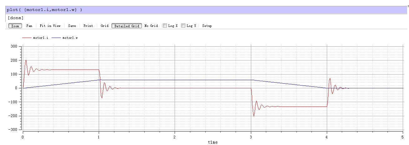
惯量为1的直流电机与一个惯量为3的惯量负载直接相连,电机电枢绕组与直流调压装置的输出相连接,一个控制器则根据速度命令信号发生器的输出和电机速度传感器的反馈,计算出一个控制指令给直流电压装置,控制电机运动。模型中给出了一个简易比例控制器的实现,但是这个控制器效果并不好,当增益较低时,稳态误差较大,当增益变大时,会引起电机电流和加速度的振荡,如下图所示。(红线为电机电流,蓝线为电机速度)
我们的仿真作业为,重写调速控制器模型Controller,并进行参数整定,实现更好的控制性能,评价指标为:
-
1)稳态速度误差尽可能小。
-
2)电机速度输出的动态特性好。
-
3)电机加减速过程中,电流平稳变化无明显振荡。
在满足上述要求的情况下,可完成仿真作业的提高要求,即把电机和惯量负载通过阻尼弹簧系统相连,阻尼系数d=0.2,弹簧系数c=10,设计控制器并整定参数,满足上述三点控制要求。
几点说明事项:
-
1)为了简化仿真,没有对调压装置和电机的电流值进行限制,但调速控制器的输出最大为正负10V,如果采用了积分控制,请考虑积分饱和效应。
-
2)鼓励使用速度环和电流环双环控制。
-
3)撰写仿真报告,说明控制器的结构,参数整定的方法和过程,对仿真结果进行分析。