【目的】
如何在2D静态磁场解释器中计算力。
Discuss how to set up a force calculation in the 2D Magnetostatic Solver.
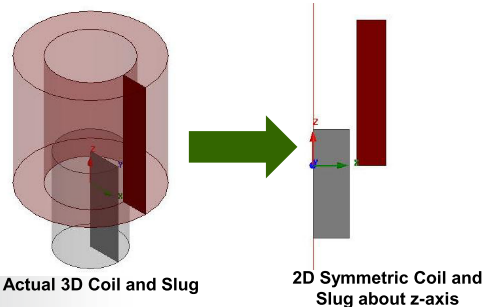
As shown in the following picture, a coil and slug are drawn in a plane using RZ symmetry. The coils carry a current that exert a vertical force on the ferromagnetic slug.
如下图所示,使用RZ对称性在平面上绘制了线圈和凸块。 线圈载有电流,该电流在铁磁块上施加垂直力。
【建模过程】
Step01:Create Design 新建设计工程文件
– Select the menu item Project -> Insert Maxwell 2D Design,然后对其进行重命名和保存
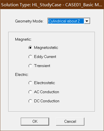
Step02:Set Solution Type 设置解释器类型(磁场分析)
– Select the menu item Maxwell 2D ->Solution Type
– Solution Type Window:
1. Geometry Mode: Cylindrical about Z
2. Choose Magnetic > Magnetostatic
3. Click the OK button
如下图:
Geometry Mode:几何模式
Cylindrical about Z,关于Z轴的圆柱体
创建基于Z轴的圆柱体,并对其磁场进行分析
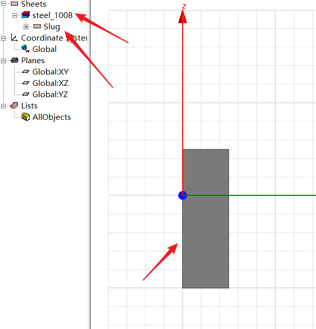
Step03: Create Slug (创建模型中的凸块)
该模型的大小为XZ平面上5*15大小的一个矩形,其对角线坐标分别是(0,0,-10)和(5,0,5),颜色设置为灰色,材料为steel_1008(冷镦钢)
– Select the menu item Draw ->Rectangle
1. Using the coordinate entry fields, enter the position of rectangle – X: 0, Y: 0, Z: -10, Press the Enter key
2. Using the coordinate entry fields, enter the opposite corner – dX: 5, dY: 0, dZ: 15, Press the Enter key
– Change the name of resulting sheet to Slug and color to Gray
– Change the material of the sheet to Steel_1008
绘制完的结果如下图所示
Step04: Create Coil (创建模型中的线圈)
该模型的大小为XZ平面上4*20大小的一个矩形,其对角线坐标分别是(6,0,0)和(10,0,20),颜色设置为棕色,材料为Copper(铜)
– Select the menu item Draw-> Rectangle
1. Using the coordinate entry fields, enter the position of rectangle – X: 6, Y: 0, Z: 0, Press the Enter key
2. Using the coordinate entry fields, enter the opposite corner – dX: 4, dY: 0, dZ: 20, Press the Enter key
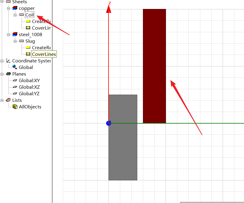
– Change the name of resulting sheet to Coil and color to Brown
– Change the material of the sheet to Copper
绘制完的结果如下图所示
Step05: Define Region(定义区域)
• Create Simulation Region
– Select the menu item Draw ->Region
– In Region window,
1. Pad all directions similarly: þ Checked
2. Padding Type: Percentage Offset
3. Value: 100
4. Press OK
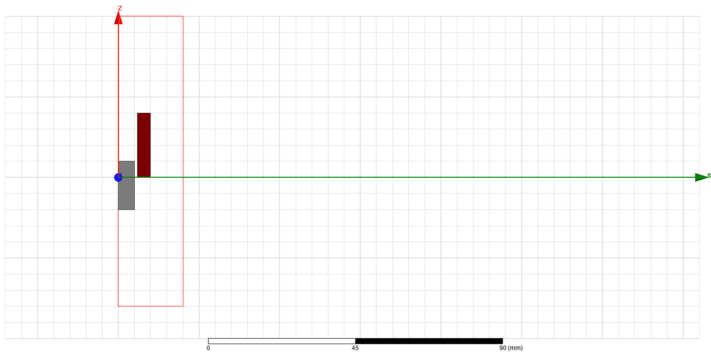
• You should see a message indicating that the –X direction is set to zero due to RZ-symmetry about the Z-axis.
绘制完的结果如下:
Step06:Assign Excitations 添加激励
• Assign Excitations 为线圈添加1000A负向电流激励
– Select the sheet Coil from history tree 首先需要选中Coil这个模型
– Select the menu item Maxwell 2D ->Excitations -> Assign -> Current
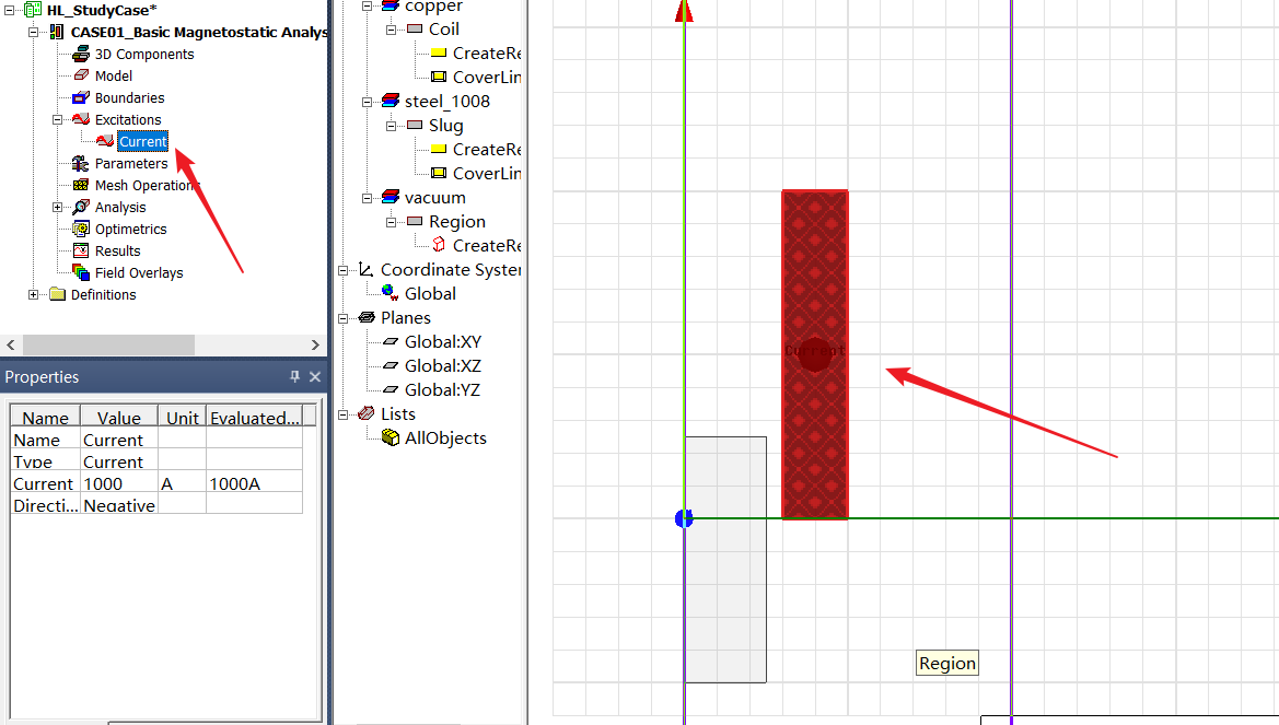
• Name: Current1
• Value: 1000
• Ref. Direction: Negative (current will be in the negative Y direction) 即电流会沿着y轴向负向流动
设置结果如下
Step07:Assign Boundary and Parameter 添加边界和参数
•Assign Boundary to Region Edges
– Select the object Region from history tree
– Select the menu item Edit -> Select ->All Object Edges
– Select the menu item Maxwell 2D -> Boundaries ->Assign -> Balloon
– In Balloon Boundary window,
• Press OK
Note: On symmetry axis, "Balloon Boundary" assignment is automatically skipped, This can also be achieved by selecting the edges of region which are not on symmetry axis.
注意:在对称轴上,将自动跳过"气球边界"分配,这也可以通过选择不在对称轴上的区域的边缘来实现。
Step08: Assign Force Calculation 添加磁力计算
– Select the object Coil from history tree
– Select the menu item Maxwell 2D -> Parameters -> Assign ->Force
– In Force Setup window,
• Press OK
Step09: Analyze 分析
• Create an analysis setup: 设置 Anslysis setup
– Select the menu item Maxwell 2D -> Analysis Setup -> Add Solution Setup
– Solution Setup Window:
1. General Tab
– Maximum Number of Passes: 15
2. Click the OK button
• Start the solution process: 开始进行仿真
– Select the menu item Maxwell 2D -> Analyze All
Step10:Solution Data 查看仿真结果数据
• View Solution Information
– Select the menu item Maxwell 2D -> Results -> Solution Data
• To View Convergence
– Select the Convergence tab
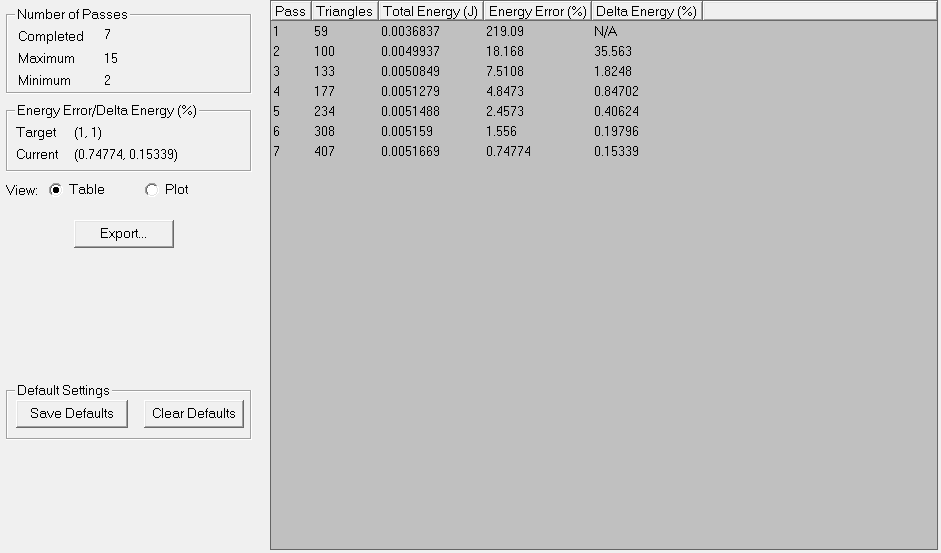
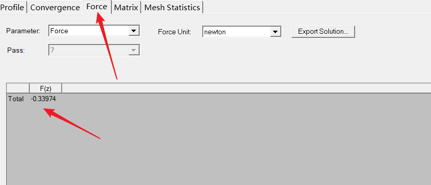
• To View Calculated Force Value
– Select the Force tab
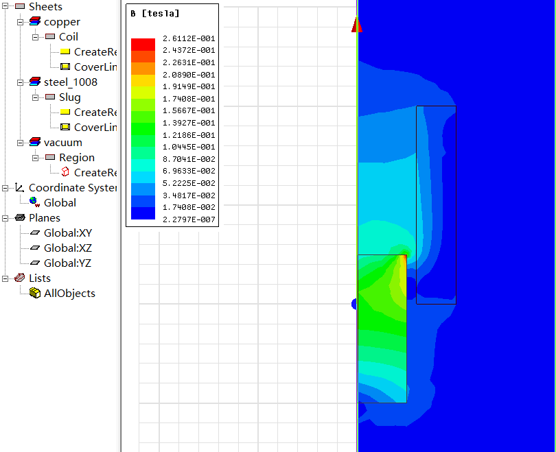
Step11:Create Field Plot 绘制磁力场
• Plot Magnetic Flux Density
– Expand the history tree for Planes
– Select the plane Global:XZ
– Select the menu item Maxwell 2D -> Fields -> Fields -> B -> Mag_B
– In Create Field Plot window,
• Press Done